



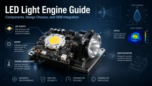
An LED light engine is more than an LED board chosen by wattage. For lighting OEMs and equipment manufacturers, it is a system whose light source, driver, PCB, optics, thermal path, connectors, and mechanical interfaces must work together inside the final product. A module that performs well on a test bench may still overheat, flicker, shift color, or produce an unacceptable beam pattern after installation.
The selection process should therefore begin with the application requirements and system constraints, not with a catalog number. Engineers must determine what the supplier will provides, what the OEM integrates, and how the complete assembly will be validated.
What Is an LED Light Engine?
The Illuminating Engineering Society (IES) defines an LED light engine as an integrated assembly containing LED packages or arrays, an LED driver, and related optical, thermal, mechanical, and electrical components. A complete LED luminaire adds the parts needed to distribute light, protect and position the components, and connect the finished unit to its power source.
Commercial terminology is not always used consistently. Some suppliers call an LED board with connectors a light engine, while others use the term only when the driver and additional system components are included. Before requesting a quotation, buyers should always confirm the actual supply boundary through a controlled specification, drawing, and bill of materials before quoting.
LED Light Engine vs LED Module vs Complete Luminaire
| Product level | Typically includes | OEM may still need to provide |
| LED module | LED source, PCB, and basic connections | Driver, heatsink, optics, controls, and housing |
| LED light engine | LED source plus defined electrical and system components | Housing and any interfaces not included in the assembly |
| LED luminaire | Complete lighting unit | Application installation and external system connection |
A basic LED module may be sufficient when the OEM already has a qualified driver, heatsink, optics, and assembly process. A more integrated light engine can reduce internal wiring and component-matching work, but it may also concentrate heat, limit serviceability, or require a supplier-specific interface.
The practical question is not simply “What is an LED light engine?” It is: Which functions should be included in the purchased assembly, and which should remain under the OEM’s control?
What Components Make Up an LED Light Engine?
LED Source, PCB, Driver, and Protection Architecture
The light source may use a COB LED, an SMD array, or another module configuration. COB can provide a compact light-emitting surface for focused or space-constrained designs, while SMD layouts can distribute light across a larger board or support multiple independently controlled channels. The choice depends on the required beam angle, board surface area, color control approach, and thermal design.
The PCB carries the source and may also include connectors, resistors, capacitors, sensors, control ICs, or driver components. Buyers comparing integrated LED module options should establish whether the quoted assembly accepts AC input, regulated DC input, constant current, or constant voltage.
Key electrical questions include:
- Does the LED light engine include the driver?
- What input voltage range is accepted?
- Is the LED current regulated on the board or externally?
- Which dimming or control methods are supported?
- What protection functions are included?
- Are the connector type, polarity, and current rating documented?
Matching only the rated wattage creates risk. Two 50 W assemblies can require different input voltages, currents, controls, and thermal conditions.
Optics, Thermal Path, and Mechanical Interfaces
The light emitting surface must be compatible with the lens, reflector, diffuser, and working distance. A change in LES size or focal position can alter center-beam intensity, cutoff, glare, and uniformity even when total lumen output remains similar.
Thermal performance depends on the full path from the LED junction through the substrate, thermal interface material, mounting surface, heatsink, and surrounding air. The U.S. Department of Energy identifies drive current, thermal path, and ambient temperature as three primary influences on LED junction temperature.
Mechanical requirements should specify:
- PCB outline and thickness
- Mounting-hole dimensions and tolerances
- Connector location and clearance
- Light-emitting surface position
- Thermal contact area
- Reference or case-temperature measurement point
- Available housing height and optical focal distance
A light engine may fit the enclosure but still fail because the thermal interface is incomplete, the connector conflicts with the housing, or the LED sits outside the optical focal position.
How to Choose the Right LED Light Engine Architecture
Integrated Driver vs External Driver
An integrated LED light engine can reduce wiring, component count, and final assembly work. It may suit compact products, modular production, or equipment in which the complete lighting assembly is replaced as one unit.
An external driver may be more appropriate when the LED operates in a high temperature area, the driver must remain accessible for maintenance, or the product requires complex controls. Separating the driver can reduce thermal coupling between the power electronics and LEDs, but it introduces additional wiring, connectors, and compatibility verification requirements.
Zhaga specifications include both light engines with separate drivers and spotlight light engines with integrated drivers, reflecting the fact that each architecture serves different product requirements.
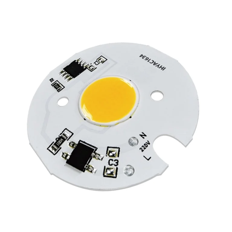
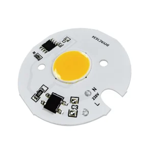
A practical example is the IHY-AC1634 integrated AC COB module.The module features 220 V, 250 mA, 50 W, available in 2700 K, 4000 K, or 6500 K output, and an aluminum PCB with dimensions of 40 × 75 × 1 mm. The emitting surface and electronic components are integrated on the board, and the PCB shape and circuit can be adapted to the structural design. Any OEM application must still verify thermal conditions, electrical protection, insulation, control compatibility, and final-product requirements.
AC, DC, Constant Current, and Constant Voltage Choices
An AC light engine is designed to accept a stated AC input through integrated electronics. It should not be confused with a bare LED module whose forward voltage happens to be described in volts. A DC input light engine may accept regulated voltage, while another module may require a dedicated constant current driver.
Selection should follow the available power architecture:
- Lowvoltage equipment may favor a DC input module.
- Products with an existing qualified driver may use a simpler LED board.
- An integrated AC architecture may reduce external components where its safety, thermal, dimming, and protection requirements can be met.
- Multichannel products may require separate regulated outputs for different colors or CCT channels.
The voltage, current, power, and control ranges should be compared directly. Zhaga’s electrical power interface work similarly emphasizes matching driver capabilities with LED-module operating requirements rather than relying on wattage alone.
Standard Module vs Custom LED Light Engine
A standard product is usually preferable when its electrical input, dimensions, LES, mounting pattern, color characteristics, and optical interface already match the equipment. It reduces nonrecurring engineering work and can simplify replacement planning.
A custom LED light engine becomes relevant when the project requires an irregular PCB, unusual emitting surface, flexible substrate, integrated controls, special spectrum, dedicated connector, restricted installation space, or fewer assembly operations.
Before requesting customization, compare the expected quantity and development cost with the value created by a better structural fit, lower assembly complexity, or differentiated optical performance. Shenzhen IHY Lighting Co., Ltd. presents application-specific LED solutions covering AC, DC, COB, and SMD modules, customized integrated sources, flexible light sources, UV/IR systems, and specialized equipment applications.
OEM Integration Checklist for an LED Light Engine
A successful OEM integration requires four connected reviews.
Electrical and control: Confirm input voltage, current, power, driver topology, dimming method, channel count, connector rating, polarity, startup behavior, and protection. Test the light engine using the intended production power supply and controller.
Thermal: Verify the substrate, thermal interface, mounting pressure, heatsink area, airflow, duty cycle, and maximum ambient temperature. Measure stabilized temperature inside the final enclosure rather than in open-air bench conditions.
Mechanical: Check PCB dimensions, tolerances, mounting holes, cable routing, connector clearance, optical alignment, and assembly stress. A board should not be forced into position or used to compensate for housing variation.
Optical and color: Validate lumens or candela, beam distribution, LES position, working distance, CCT, CRI, color tolerance, glare, and uniformity in the completed device. Optical results from a bare board may not represent the finished product.
Interface standardization can make replacement and multi-supplier integration easier, but it does not replace product-level validation. Zhaga standardizes interfaces between modules, drivers, holders, connectors, and other luminaire components to support interoperability while allowing component designs to differ.
Common LED Light Engine Problems and How to Prevent Them
Overheating, reduced output, flicker, color shift, and poor beam quality often originate outside the LED package itself.
An overheating light engine can be caused by over driving, an undersized heatsink, poor thermal contact, or exposed to higher ambient temperature than expected. Output loss and color shift may follow rising junction temperature or long term stress. LED reliability is closely related to junction temperature and the performance of the complete thermal management system.
Flicker can result from driver mismatch, unstable input power, incompatible dimming, poor connections, or control settings. Uneven illumination may be caused by the wrong lens, incorrect focal distance, insufficient diffusion, component spacing issues, or mechanical misalignment.
A systematic troubleshooting approach typically includes:
- Measure the actual electrical input and current.
- Check connections and control signals.
- Record stabilized case and ambient temperatures.
- Inspect the thermal interface and mounting pressure.
- Test the optics and beam in the final housing.
Replacing the LED board without identifying the system cause may allow the same failure to recur.
Replacement, Serviceability, and Lifecycle Planning
Two LED light engines with the same wattage are not necessarily interchangeable. A compatible replacement must match the electrical input, driver behavior, dimensions, mounting, thermal contact, LES position, optics, and controls.
OEMs should also ask about product life-cycle, material-change notifications, approved alternatives, traceability, and spare-part strategy. Standardized or socketable modules may support easier replacement where the luminaire has been designed around the relevant interface. Zhaga’s replaceable-module specifications illustrate how defined mechanical and electrical interfaces can support serviceability and interoperability.
How to Prepare an LED Light Engine RFQ and Evaluate a Supplier
A useful RFQ should include the application, drawings, available dimensions, input conditions, target output, beam requirements, working distance, CCT, CRI, control method, ambient temperature, duty cycle, prototype quantity, and estimated annual demand.
Supplier evaluation should cover more than the ability to manufacture an LED board. A suitable engineering partner should be able to review the interaction between the source, PCB, driver, optics, thermal path, and mechanical structure. Buyers should request controlled drawings, defined test conditions, sample-approval criteria, material traceability, and a Product Change Notification (PCN) .
Shenzhen IHY Lighting Co., Ltd. specializes in structural design, optical engineering, electrical development, smart controls, with a focus on integrating COB sources, drivers, passive components, and power management on a single PCB. Its custom COB LED light engine manufacturer capabilities are relevant when a project requires more than a standard light source or isolated module.
Conclusion
Choosing an LED light engine requires a system level review. Define the supply boundary, choose the driver location and input architecture, confirm electrical, thermal, mechanical, and optical compatibility, and validate the assembly inside the finished equipment.
For an initial project review, prepare the model or concept, drawings, dimensions, input power, optical targets, operating environment, sample quantity, expected volume, and any available failure photos. These details can be used to submit a light engine project inquiry to Shenzhen IHY Lighting Co., Ltd. without assuming that a standard or custom architecture is appropriate before the requirements are reviewed.
Frequently Asked Questions About LED Light Engines
Does an LED light engine include the driver?
The formal IES definition includes an LED driver, but commercial product naming varies. Verify the BOM, input requirements, and driver configuration against the supplier’s datasheet.
LED module vs LED light engine: what’s the difference?
An LED module normally contains the LED source and PCB. A light engine has a higher level of system integration and may include the driver, connectors, controls, optics, or defined thermal and mechanical interfaces.
Can an LED light engine connect directly to AC power?
Only a product specifically designed and documented for AC input should be connected to AC power. A bare LED module normally requires an appropriate driver. Check the rated input, protection, insulation, and final application requirements.
Can one LED light engine replace another with the same wattage?
Not based on wattage alone. Compare voltage, current, driver type, dimensions, mounting, thermal contact, LES position, beam requirements, connectors, and controls before approving a replacement.
When should an OEM use a custom LED light engine?
Customization may be justified when standard products cannot meet the required PCB shape, installation space, LES, spectrum, voltage, controls, connector layout, thermal path, or assembly strategy.