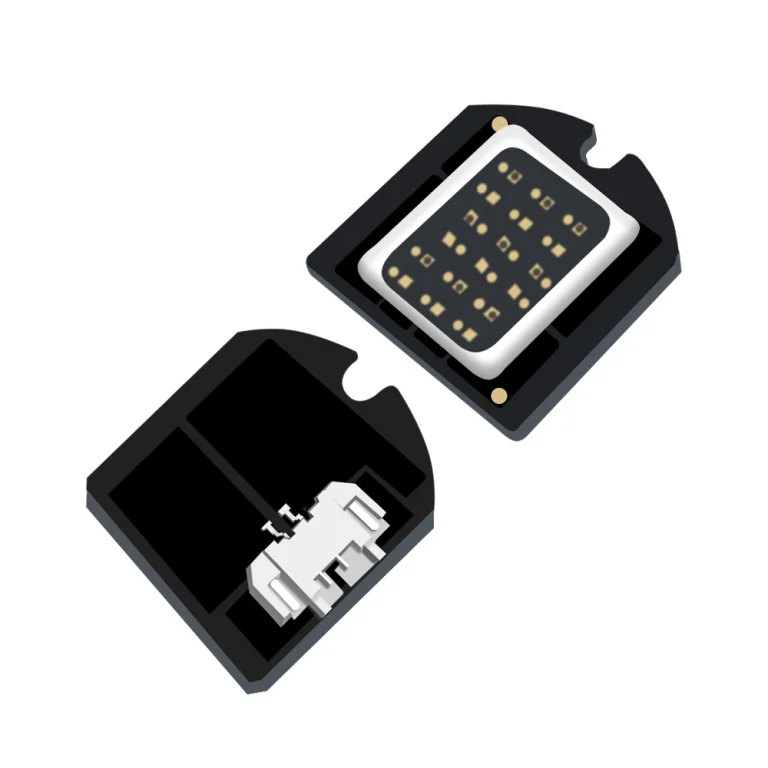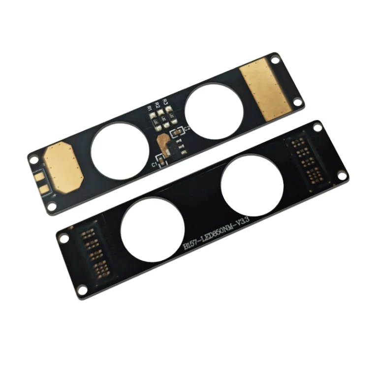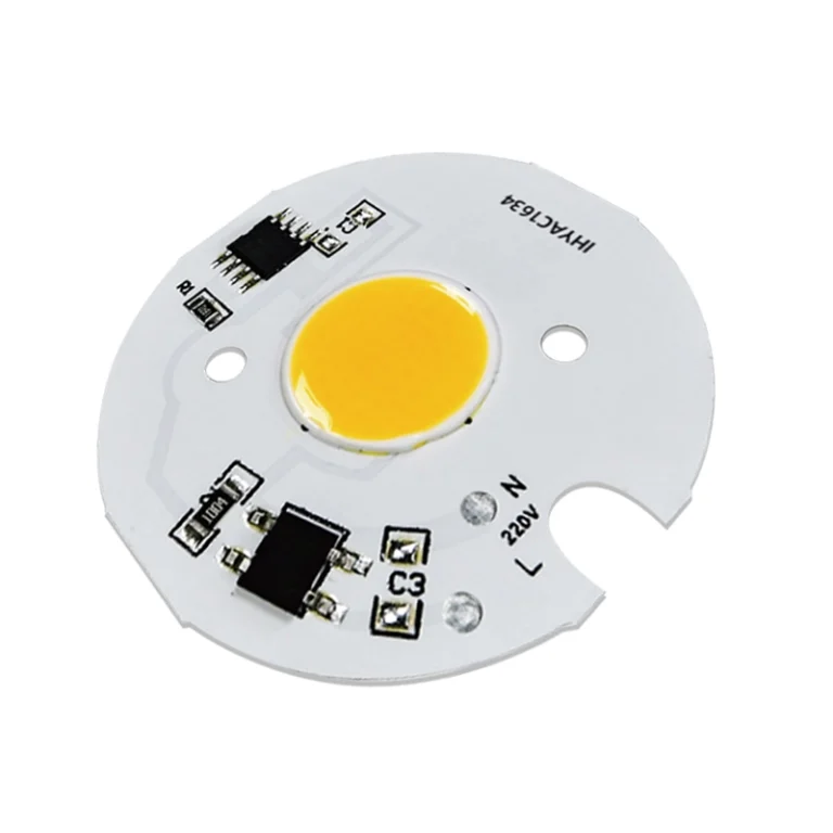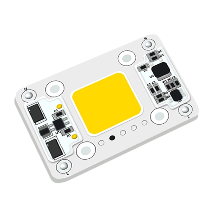




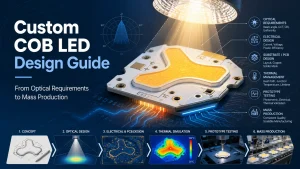
A successful custom COB LED design starts with the application not with a wattage, voltage, or preferred board shape. When a standard COB cannot match the required light emitting surface (LES), beam pattern, available space, spectrum, electrical input, or control method, an OEM may need a custom light source. The challenge is translating those product requirements into a specification that can be designed, tested, and manufactured reliably.
A prototype that illuminates correctly is only the beginning. The COB must also work with the final driver, optics, heatsink, enclosure, connectors, and operating environment. Each interface should be defined before the design moves into mass production.
When Does an OEM Need a Custom COB LED?
Standard COB Limitations That Justify a Custom Design
A standard COB is usually the practical choice when its dimensions, light emitting surface, voltage, current, color characteristics, and mounting interface already match the product. Customization adds engineering work and should solve a specific limitation rather than simply create a different part number.
A custom COB LED may be justified when the equipment requires:
- A nonstandard PCB outline or luminous pattern
- A restricted lightemitting surface for compact optics
- A flexible, curved, annular, or sideemitting structure
- A voltage or current arrangement matched to the existing power system
- Multiple CCT, color, visible, infrared, or ultraviolet channels
- Integrated connectors, controls, sensors, or supporting electronics
- Reduced internal wiring or assembly operations
Before requesting a completely new design, determine whether the problem can be resolved through a different lens, reflector, driver, heatsink, or standard package. A custom source may be unnecessary when the required change concerns only the surrounding fixture.
Shenzhen IHY Lighting Co., Ltd. publicly lists custom shape, flexible, high power, automotive, photography, and IR/UV products within its custom COB LED options, illustrating the range of structural and application requirements that may lead an OEM beyond a standard circular or square COB.
Define the Optical Requirements Before Designing the COB
Light Output, Working Distance, Beam Pattern, and LES Size
Terms such as “brighter,” “more focused,” or “more uniform” are not sufficient design inputs. A supplier needs measurable performance targets and the conditions under which they apply.
The correct starting point depends on how the equipment uses the light:
| Application requirement | Parameters to define |
| Illuminate a target at distance | Candela, beam angle, working distance, target diameter |
| Produce uniform close-range fill | Emitting area, diffuser distance, luminance uniformity |
| Fit a compact spotlight optic | LES size, focal position, lens or reflector diameter |
| Cover a wide area | Beam distribution, edge falloff, optical losses |
| Support imaging or inspection | Spectrum, uniformity, flicker, working distance |
Total lumens describe overall light output but do not show how much light reaches a target. A narrow beam may require center beam intensity and working-distance lux values, while a close range fill light may require a larger, more uniform luminous surface.
The light-emitting surface, or LES, also affects optical control. A smaller LES can make it easier to create a concentrated beam, but concentrating substantial power into a smaller area can increase local thermal demands. A larger emitting area may improve uniformity, yet it may not fit a compact reflector or provide the required intensity at distance.
Engineers should provide the intended working distance, desired beam diameter, available optical space, and target output before finalizing the COB dimensions. The source should be developed with the lens, reflector, or diffuser—not selected independently and matched afterward.
CCT, CRI, Color Tolerance, Spectrum, and Channel Control
White-light applications normally require a target correlated color temperature and color-rendering requirement. Depending on the product, the specification may also need R9, color tolerance, Duv, TLCI, or a spectral distribution rather than a general request for “high CRI.”
Specialized equipment may require more detailed optical inputs:
- Photography and imaging systems may need stable color reproduction across dimming levels.
- Inspection equipment may require a defined spectrum that increases contrast for a target material.
- Medical-support or aesthetic devices may use visible, infrared, or ultraviolet wavelengths.
- Tunablewhite or multi color products need separate electrical specifications for each channel.
- Brand marks and illuminated symbols may require uniform brightness across an irregular luminous outline.
A multichannel COB design affects more than color. Each channel may have a different forward voltage, current requirement, chip arrangement, and heat contribution. The driver and control system must operate the channels independently while maintaining acceptable color mixing and thermal balance.
Purchasers should specify the required channels, output from each channel, control method, dimming range, and measurement conditions. Color and spectrum should be checked after the COB reaches a stable operating temperature because electrical loading and thermal conditions may affect the measured result.
Select the Electrical and Control Architecture
Voltage, Current, Driver, Dimming, and Channel Configuration
The COB’s electrical architecture should be developed around the equipment’s available power and control system. Specifying power alone is not enough. Two COBs with the same rated wattage may require very different voltage and current combinations.
A low voltage, high current design may fit battery powered or existing low voltage equipment, but it can require larger conductors, suitable connectors, and careful management of voltage drop. A higher voltage, lower current arrangement may reduce current in the wiring but requires a compatible driver and appropriate product-level electrical design.
The RFQ should clarify:
- Available input power
- Preferred or existing driver topology
- Target COB forwardvoltage range
- Rated operating current and maximum power
- Dimming method
- Number of independently controlled channels
- Connector, terminal, or solderpad preference
- Whether supporting electronic components should be integrated
An external constant-current driver may be suitable when the OEM already has a qualified power architecture or wants the driver separated from the LED’s thermal zone. A more integrated module may reduce wiring and assembly, but onboard electronics can affect PCB space, heat distribution, maintenance, and compliance responsibilities.
The COB, driver, and controller should be tested together before the mechanical design is frozen. Common risks include insufficient driver voltage range, excessive current, unstable low-level dimming, incorrect channel wiring, and connector losses in high current systems.
Choose the PCB, Substrate, and Mechanical Interface
Aluminum, Ceramic, FPC, or FR4, Which Substrate Fits the Application?
Substrate selection depends on power density, heat flow, mechanical structure, insulation needs, thickness, and flexibility. The material name alone does not define performance; the complete construction, including copper, dielectric, thickness, and mounting interface, should be reviewed.
Aluminum substrates are commonly considered when the COB needs a rigid board and a direct thermal path to a heatsink. Ceramic may be evaluated for compact designs with demanding thermal or electrical requirements. FPC is useful when the light source must bend, follow a curve, or fit a thin structure, but bending direction, radius, repeated movement, heat spreading, and mechanical support must be defined. FR4 may be suitable for lower thermal loads or supporting electronics, although it should not be assumed to provide the same heat path as a purpose-designed metal or ceramic substrate.
Procurement specifications should state:
- Substrate type and thickness
- Board outline and copper requirements
- Thermal contact area
- Required flexibility and bending direction
- Installation method
- Environmental exposure
- Whether the board must carry control or power components
Material properties and acceptable operating limits may vary by construction and supplier. They should be verified against the proposed design rather than copied from a generic material comparison.
PCB Shape, Mounting, Connectors, and Tolerances
Custom-shape COB LEDs are useful when the luminous surface must follow a product outline, logo, ring, symbol, curved structure, or restricted enclosure. However, an unusual shape can reduce usable thermal area, complicate chip placement, create mechanical stress, or leave insufficient room for conductors and electronic components.

A controlled drawing should identify the board outline, luminous region, mounting holes, datum points, connector orientation, polarity, prohibited areas, thermal contact surface, and critical tolerances. A housing photograph or hand sketch may help communicate the concept, but it is not a substitute for an approved engineering drawing.
The IHY-A15 custom-shape COB LED is a practical example of the relationship between luminous geometry, PCB shape, and electronics. Its published configuration is 12 V, 1500 mA, 30 W, and 10000 K on a 386 × 205 × 1.5 mm aluminum substrate. The product page also describes custom luminous patterns and integrated IC and driver functions. An OEM evaluating a similar structure would need to define the exact outline, uniformity target, connection points, mounting references, and operating conditions before sample approval.
Design the Complete Thermal Path and Prevent Early Failure
Power Density, Thermal Interfaces, Derating, and Final-Housing Validation
Thermal design should begin with the complete path from the LED junction through the substrate, interface material, mounting surface, heatsink, enclosure, and ambient air. A thermally capable COB cannot compensate for poor contact pressure, an uneven mounting surface, an undersized heatsink, or trapped heat inside the finished equipment.
The U.S. Department of Energy identifies junction temperature as a major factor affecting LED light output and notes that temperature is influenced by drive current, the thermal path, and ambient conditions.
Power density is particularly important in custom designs. Reducing the LES while maintaining the same input power can increase local heat concentration. Adding onboard electronics can create additional heat near the LEDs. A product that runs correctly in open air may overheat after installation behind a lens, cover, seal, or compact enclosure.
Thermal validation should use:
- The intended production driver
- The final or representative housing
- The specified thermal interface material
- The actual mounting method and pressure
- The intended duty cycle
- The maximum expected ambient condition
- Stabilized temperature measurements
When temperatures exceed the design target, corrective actions may include lowering drive current, increasing thermal contact area, modifying the board, separating heat producing components, improving the heatsink, or changing the enclosure. Replacing the COB alone may not resolve a system level thermal problem.
Turn Application Requirements Into a Manufacturable Specification
Drawings, Tolerances, Materials, Interfaces, and DFM
A custom COB specification should create one shared definition for the OEM, supplier, quality team, and assembler. It should combine optical, electrical, thermal, and mechanical requirements rather than treating them as separate purchasing notes.
The specification should include:
- Application and operating environment
- Optical targets and test distance
- LES and luminousarea dimensions
- CCT, CRI, spectrum, or wavelength
- Voltage, current, power, and channel configuration
- PCB outline, material, thickness, and mounting
- Connector or terminal details
- Thermalinterface assumptions
- Critical dimensions and tolerances
- Prototype and validation requirements
Critical functional dimensions should be controlled by the OEM. Noncritical areas can be left open for supplier DFM recommendations when doing so improves routing, assembly, heat spreading, or manufacturability.
Before prototype production, both parties should approve the drawing revision, scope of supply, intended materials, and measurement conditions. Without a controlled specification, a sample can appear acceptable while the supplier and purchaser still hold different assumptions about performance or production variation.
Prototype and Validate the Custom COB LED
Optical, Electrical, Thermal, and Mechanical Sample Testing
Prototype approval should verify more than appearance and initial illumination. The sample should be tested in conditions that represent the final equipment.
A practical validation plan may include:
- Light output, intensity, beam pattern, and uniformity
- CCT, CRI, spectrum, and channel mixing
- Voltage, current, power, startup, and dimming behavior
- Stabilized case and ambient temperatures
- Dimensions, mounting, connectors, and assembly clearances
- Performance with the final lens, reflector, diffuser, and driver
Measurement conditions should be recorded. The Illuminating Engineering Society’s LM-85 method addresses reproducible optical and electrical measurement of solid-state lighting sources, reinforcing the importance of defined test conditions when comparing or approving LED components.
Testing one COB briefly at room temperature is not sufficient for a design intended to operate in an enclosed or thermally demanding product. Sample quantities and acceptance criteria should reflect the risk of the application.
Common Prototype Failures and Corrective Actions
Typical prototype problems include overheating, dark zones, nonuniform luminous patterns, unexpected beam shapes, color variation, flicker, unstable dimming, connector heating, and mechanical interference.
Root-cause analysis should follow the system:
- Confirm the electrical input and actual operating current.
- Measure stabilized temperatures and inspect the thermal interface.
- Check the LES position and optical alignment.
- Review PCB routing, chip distribution, and luminous geometry.
- Inspect mounting stress, connectors, and enclosure clearances.
A current reduction may resolve overheating but also lower output below the target. More diffusion may improve uniformity while reducing intensity. A corrective action should therefore be tested against all affected requirements rather than only the visible symptom.
Each prototype revision should record the issue, suspected cause, design change, and verification result. This creates a clearer path toward design freeze and production approval.
Move From Prototype to Mass Production
Golden Sample, Binning, Tolerances, Traceability, and Change Control
A golden sample is useful only when it is tied to an approved drawing and measurable acceptance criteria. Visual comparison alone cannot control electrical, color, dimensional, or thermal variation.
Before production, define acceptable ranges for output, CCT, voltage, current, dimensions, luminous uniformity, and any application specific characteristics. Binning requirements should reflect how much variation the finished equipment can tolerate across units and production lots.
The purchasing agreement should also define:
- Approved material and component boundaries
- Lot or batch traceability
- Sample retention
- Handling of nonconforming material
- Notification of material, process, or design changes
- Conditions requiring revalidation
If an LED die, phosphor, substrate, connector, IC, or other critical component changes, the effect on output, color, heat, fit, and control should be reviewed before the revised version is accepted.
How to Prepare a Custom COB LED RFQ
Required Optical, Electrical, Mechanical, Thermal, and Commercial Inputs
An effective RFQ allows suppliers to quote the same scope and identify technical risks early. At minimum, include the product application, drawings, available space, working distance, optical target, input power, operating environment, sample quantity, and expected production demand.
Do not send only “30 W, white, custom shape.” That description leaves the supplier to guess the LES, CCT, current, substrate, thermal interface, control method, and acceptance criteria.
When unusual shapes, flexible structures, integrated controls, or specialized spectra are involved, broader application-specific LED solutions may be more appropriate than requesting an isolated COB package. IHY’s solution portfolio publicly includes flexible light sources, AC/DC/COB/SMD modules, integrated sources, UV/IR systems, and professional equipment applications.
How to Evaluate a Custom COB LED Manufacturer
Engineering Evidence to Request Before Approving Production
A custom supplier should be evaluated on the ability to convert an application into controlled engineering documents—not only on whether it can produce an illuminated sample.
Ask for evidence such as:
- A dimensional drawing and defined supply boundary
- Electrical and optical specifications with test conditions
- Thermal assumptions and installation requirements
- A prototype and revision plan
- Material identification and traceability
- Production acceptance criteria
- A process for design and component changes
Shenzhen IHY Lighting Co., Ltd. describes its work as covering structural design, optical engineering, electrical specifications, smart controls, and the integration of COB sources, drivers, passive components, and power-management functions on a single PCB. These capabilities make its custom COB LED light engine manufacturer positioning relevant to projects that require coordinated optical, electrical, and mechanical development rather than a standard COB alone.
The final supplier decision should still be based on the specific proposal, approved documents, prototype results, and production requirements for the project.
Conclusion
Custom COB LED design should move in a controlled sequence: define the optical target, select the electrical architecture, choose the substrate and mechanical interface, validate the full thermal path, approve the prototype in the final equipment, and lock the production specification.
For an initial technical review, prepare the application, drawings, available dimensions, input conditions, beam or output target, color or spectrum requirements, thermal environment, sample quantity, expected volume, and any existing failure photographs. These materials can be used to submit a custom COB LED project inquiry to Shenzhen IHY Lighting Co., Ltd. without assuming in advance that a fully custom design is required.
Frequently Asked Questions About Custom COB LED Design
What specifications are needed for a custom COB LED?
Provide the application, working distance, target output, beam, LES limits, CCT or spectrum, voltage, current, power, control method, PCB dimensions, substrate preference, mounting, thermal conditions, and estimated quantity.
Can a COB LED be made in any shape?
Many nonstandard shapes are possible, but feasibility depends on PCB layout, chip placement, thermal area, electrical routing, encapsulation, dimensions, and manufacturing constraints. The proposed outline should undergo a DFM review.
Which substrate is best for a custom COB LED?
There is no universal choice. Aluminum, ceramic, FPC, and other substrates suit different thermal, thickness, flexibility, insulation, and mechanical requirements. The complete board construction and operating conditions should be evaluated.
How should a custom COB LED prototype be tested?
Test it with the intended driver, optics, heatsink, housing, control system, duty cycle, and ambient conditions. Verify optical, electrical, thermal, color, dimensional, and mechanical performance against written acceptance criteria.
When should an OEM choose a custom COB instead of a standard module?
Customization is appropriate when a standard product cannot meet a critical requirement such as LES, PCB shape, voltage, spectrum, channel configuration, flexibility, mounting, thermal interface, or integrated-control needs.