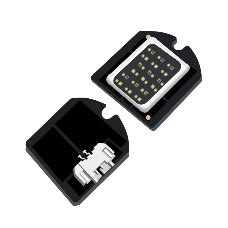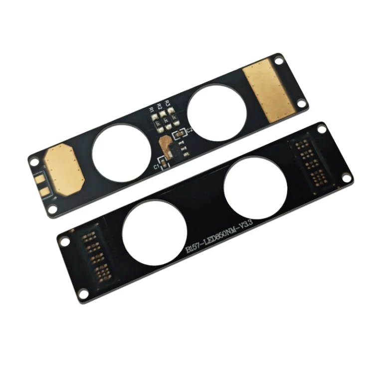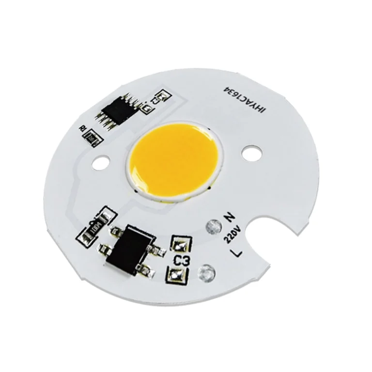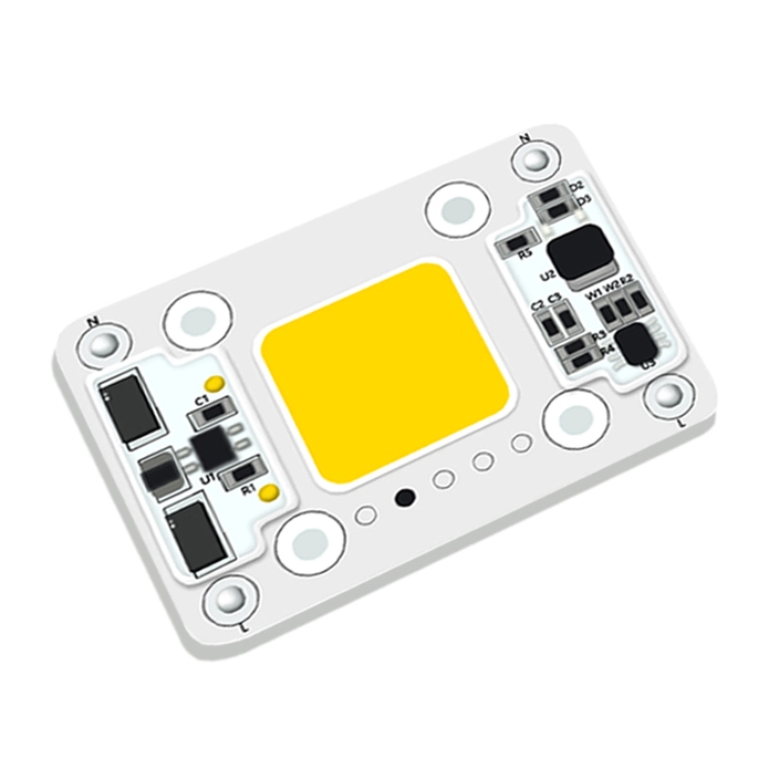




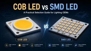
Choosing between COB LED and SMD LED is not simply a matter of selecting the brighter, cooler, or inexpensive version. For lighting OEMs, equipment manufacturers, engineers, and maintenance teams, the better choice should depends on the required beam, available PCB area, thermal path, driver design, color control needs, assembly process, and total cost of the whole system.
COB often suit for products that need a compact, continuous light emitting surface and high light density. SMD LED arrays often suit for super high power modules, distributed illumination, multichannel control, and designs that use established surface mount assembly processes. Of course, not any single process is suitable for all lighting products or lighting requirements.
COB LED vs SMD LED: Quick Selection Matrix
A COB LED combines multiple bare LED dies on a shared substrate beneath a common phosphor layer. The close die spacing can produce substantial light output from a relatively small light emitting surface. SMD LEDs are individually packaged components mounted on a PCB, allowing designers to control component spacing, circuit layout, color channels, and distribution across a larger area.
The following matrix provides a practical starting point. Final performance must still be verified in the completed lighting system.
| Decision factor | COB LED | SMD LED array | What the buyer should verify |
| Light-emitting surface | Compact and continuous | Distributed individual sources | LES, LED spacing, diffuser distance |
| Beam control | Well suited to compact reflectors and lenses | Flexible for wide or distributed patterns | Beam angle, intensity distribution, optical losses |
| Light uniformity | Can reduce visible multiple-source effects | Depends heavily on spacing and diffusion | Hot spots, shadows, color uniformity |
| PCB layout | Concentrated source area | Greater placement flexibility | Available area, routing, thermal copper |
| Color control | Possible with specially designed multichannel COBs | Flexible for separate colors and channels | Channel count, mixing distance, driver design |
| Thermal design | Concentrated thermal load | Heat distributed across the PCB | Case temperature, thermal resistance, heatsink |
| Assembly | May reduce component count | Compatible with standard SMT workflows | Yield, soldering, handling, test process |
| Repairability | Source is generally replaced as one unit | Individual components may be serviceable | Field-service strategy and spare parts |
| System cost | May simplify optics and assembly | May offer sourcing and layout flexibility | Complete BOM, not only LED unit price |
Choose COB When the Design Needs a Compact, Uniform Light Source
COB is often the better choice when a product needs a small light emitting surface, focused output, a single optical center, or reduced multiple shadow effects to achieve dot-free and more even illumination.Typical examples include spotlights, portable work lights, cycling lights, inspection equipment, and compact high output fixtures.
Good LED should not be decide by wattage alone. Engineers should confirm the size of COB’s light emitting surface(LES), target lumens or candela, beam geometry, operating current, case temperature, CRI, CCT, and compatibility with the intended lens or reflector. For example, a high power COB may be unsuitable when the housing lacks sufficient thermal contact area or when the driver cannot deliver the required current reliably.
Projects requiring nonstandard dimensions, electrical characteristics, or emitting shapes can be compared against available custom COB LED rather than forcing a standard COB into an unsuitable mechanical design.
Choose SMD When the Design Needs Distributed Light or Flexible Control
SMD arrays are often appropriate when light must be distributed across a panel, long PCB, curved arrangement, or wide illuminated area. They also provide flexibility for tunable white, RGB, RGBW, indicator, and independently controlled lighting channels.
However, SMD is not automatically the better choice for wide beam illumination. Poor LED spacing or insufficient diffuser distance can create visible dots, uneven luminance, multiple shadows, or color separation. Buyers should confirm package dimensions, binning, PCB spacing, reflow requirements, drive current per channel, diffusion distance, and thermal copper design.
For equipment requiring the LED source, connectors, driver components, or control circuitry in one assembly, custom integrated LED modules may reduce internal wiring and final assembly work compared with purchasing individual components separately.
Why COB vs SMD Comparisons Often Give Conflicting Answers
Searches for “COB or SMD LED—which is better?” frequently produce contradictory claims. One comparison may state that COB is brighter and more efficient, while another gives the advantage to SMD. These disagreements usually occur because the products were not compared under the same conditions.
Compare the Complete Lighting System, Not the Package Name Alone
A fair COB vs SMD efficiency comparison requires equivalent system input power, CCT, CRI, operating temperature, driver efficiency, and optical losses. Comparing the rated output of a bare COB with the measured output of a complete SMD fixture produces a misleading result.
Brightness also needs a clear definition. Lumens measure total light output, while candelas measure intensity in a specific direction. A compact COB may produce higher center beam intensity when paired with a suitable reflector, even when an SMD array produces similar total lumens over a wider area.
The same logic applies to power consumption and service life. Buyers should request test conditions alongside performance figures, including drive current, measurement temperature, stabilization time, and whether the figures apply to the LED source or the complete luminaire.
Separate Package Level Advantages From Fixture Level Results
A compact COB light emitting surface can simplify optical alignment and support high light density. That does not automatically mean that every COB fixture has lower glare, better efficacy, or longer life.
Final results depend on the driver, heatsink, thermal interface material, reflector, lens, diffuser, enclosure, and operating environment. An SMD array with well-designed spacing and thermal distribution may outperform a poorly integrated COB. A properly matched COB system may outperform an SMD layout that requires excessive diffusion or suffers from optical losses.
The practical solution is to evaluate the package inside the intended housing and optics, not as an isolated component.
COB vs SMD Performance, Reliability, and Total Cost
Brightness, Beam Control, Uniformity, and Glare
COB often fits focused lighting because a small LES can be easier to position at the focal point of a compact reflector or lens. SMD arrays provide more freedom to spread light across a wider PCB and shape the distribution through component placement.
Neither package has a fixed beam angle. The finished beam is determined by the source geometry and secondary optics. During sample approval, buyers should review a photometric distribution or test the unit at the intended working distance. Total lumens alone will not reveal center intensity, edge falloff, multiple shadows, hot spots, or glare.
For photography, inspection, medical support, and close range fill lighting, color uniformity across the beam may be as important as peak output. The LED arrangement, phosphor consistency, diffusion system, and thermal balance should all be evaluated.
Efficacy, Heat Dissipation, and Service Life
The question “Does COB LED produce more heat than SMD LED?” cannot be answered from the package name alone. Heat depends on electrical input, efficiency, drive current, power density, substrate, thermal interface, heatsink, airflow, and ambient temperature.
COB concentrates power in a smaller region, which can provide a direct thermal path but may create a demanding localized heat load. SMD spreads heat across the PCB, but inadequate copper, crowded placement, or poor enclosure ventilation can still produce high junction temperatures.
The U.S. Department of Energy notes that LED reliability is closely associated with junction temperature, which is influenced by drive current and the complete thermal management system. Buyers should therefore require stabilized thermal testing in the final housing. Derating the LED, improving contact pressure, selecting an appropriate thermal interface, and checking driver heat are more useful preventive actions than assuming one package will last longer.
PCB, Assembly, Repairability, and Total System Cost
A valid COB vs SMD cost comparison must include more than the LED purchase price:
- LED source or package cost
- PCB material and area
- SMT or assembly cost
- Driver and protection components
- Connectors and internal wiring
- Lens, reflector, and diffuser
- Heatsink and thermal interface
- Inspection and functional testing
- Rework, warranty, and field replacement
COB may reduce the number of mounted LED packages and simplify optical alignment. SMD may provide broader sourcing options, mature automated placement, and easier adjustment of component distribution. The more economical choice depends on production volume, assembly capability, optical requirements, and service strategy.
Which LED Package Fits the Application?
Focused, High Intensity, and Space-Constrained Products
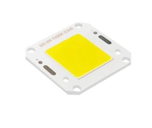
A COB should be evaluated when the product needs concentrated output from a defined optical center and has enough heatsink area behind the source. Portable work lights, cycling lights, compact outdoor fixtures, and inspection systems are common examples.
IHY-YN50 6V 50W low voltage high power COB show us why electrical and thermal checks matter. Its published specifications include 6V, 8A, 50W, 4000K, a 46 × 40 × 2 mm aluminum substrate, and options for customized shapes and specifications. We should consider about this type of source must verify high current driver capacity, conductor sizing, connector losses, thermal contact, and optical compatibility before approval before we make decision.
SMD may remain preferable when the available heatsink cannot support concentrated power or when the design needs several separately positioned beams.
Distributed, Multichannel, and Color Controlled Products
SMD arrays are commonly selected for area lighting, backlighting, tunable-white systems, and products requiring separate color channels. Component placement can be adjusted to match a panel shape or distribute heat over a larger PCB.
A custom multichannel COB can also provide several colors or CCT channels within one emitting area. It may suit equipment that needs compact color mixing, but the driver must independently control each channel, and the optical system must prevent color separation. Buyers should check channel current, thermal interaction, dimming behavior, CCT range, CRI, and color consistency at different output levels.
Can an SMD LED Array Be Replaced With a COB LED?
Replacing an SMD board with a COB is rarely a simple component swap. The redesign should pass four compatibility checks:
- Electrical:forward voltage, operating current, power, driver topology, dimming, and protection.
- Thermal:substrate, thermal resistance, contact area, interface material, and heatsink capacity.
- Mechanical:dimensions, mounting holes, connectors, clearances, and enclosure fit.
- Optical:LES position, focal distance, beam angle, reflector opening, and diffuser behavior.
A source that lights successfully during a bench test may still overheat, flicker, shift color, or produce an unacceptable beam after installation. Prototype testing should include thermal stabilization, repeated switching, functional test, optical measurements, and operation at the expected ambient temperature.
LM-80 data can support lumen maintenance evaluation for LED packages, arrays, or modules, but it doesn’t by itself establish the service life of the complete fixture. Drivers, optics, connections, seals, and thermal design can fail or degrade independently.
Standard COB, SMD Array, or Custom LED Light Engine?
A standard package is usually appropriate when its voltage, power, LES, mounting pattern, spectrum, and optical compatibility already meet the project requirements. Customization becomes more relevant when the product requires an irregular PCB, flexible substrate, unusual emitting surface, integrated electronics, dedicated connector, specific spectrum, or reduced assembly work.
The Illuminating Engineering Society defines an LED light engine as an integrated assembly that may include LED packages or arrays, a driver, and optical, thermal, mechanical, and electrical components.
Shenzhen IHY Lighting Co., Ltd. develops COB sources and modules around structural, optical, and electrical requirements. Its website presents COB, AC and DC modules, UV and IR modules, flexible sources, custom shapes, and integrated PCB solutions. These options can be reviewed through Shenzhen IHY Lighting Co., Ltd. when a project cannot be satisfied by a standard source.
How to Prepare an RFQ and Evaluate a Supplier?
An effective RFQ should state the application, available dimensions, target output, working distance, beam requirement, input voltage, operating current, power limit, CCT, CRI, control method, ambient temperature, duty cycle, annual quantity, and required validation documents,it will be better that you could provide original documents of the drawings.
A qualified supplier should be able to review interactions between the LED source, driver, PCB, thermal path, optics, and mechanical structure. Buyers should request a controlled specification, dimensional drawing, sample plan, test conditions, material identification, batch-traceability approach, and process for communicating design or material changes.
Shenzhen IHY Lighting Co., Ltd. describes its offering as a combination of COB, driver, optics, and application-specific integration. Its product range includes custom integrated LED modules for projects that require more than an isolated LED package. Before mass production, the selected design should still be verified against the approved drawing, operating conditions, and sample test results.
Conclusion
The correct choice between COB LED and SMD LED depends on the complete lighting system. COB is often suitable for compact, high density, optically focused designs. SMD is often suitable for distributed layouts, flexible placement, and multichannel control. Brightness, efficiency, heat dissipation, lifespan, and cost must be compared under equivalent operating conditions.
For a project review, prepare the application, drawings, available dimensions, input conditions, optical targets, operating environment, sample requirements, and estimated quantity. These details can be used to submit a lighting project inquiry to Shenzhen IHY Lighting Co., Ltd. for a source or module recommendation without assuming that either COB or SMD is automatically the correct answer.
FAQs
Is COB LED always brighter than SMD LED?
No. A COB can provide high light density from a compact emitting surface, but total brightness depends on power, efficacy, temperature, driver performance, and optics. Compare lumens and candela under equivalent test conditions.
Which is more energy efficient, COB or SMD LED?
Either can be efficient. The result depends on the selected device, drive current, CRI, CCT, junction temperature, driver losses, and optical losses. System level lumens per watt are more useful than package level claims.
Does a COB LED require a larger heatsink?
Not necessarily, but a high-power COB may concentrate heat in a smaller area. Heatsink requirements should be calculated from power, thermal resistance, case temperature limits, ambient temperature, and available airflow.
Which lasts longer, COB or SMD LED?
Neither has a universal lifespan advantage. Junction temperature, drive conditions, materials, thermal design, environmental exposure, and driver quality determine reliability. Verify the complete fixture rather than relying only on LED package data.
Can an SMD LED board be replaced by a COB module?
Only after checking voltage, current, driver topology, thermal contact, dimensions, mounting, LES position, and optics. A redesign and prototype validation are often required.