



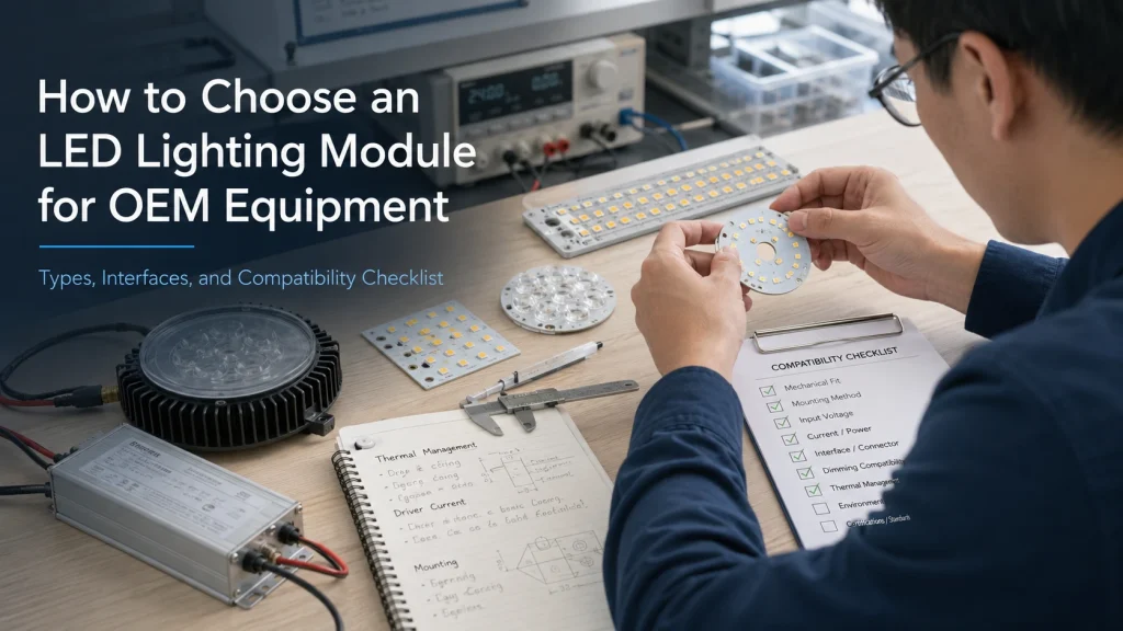
Choosing an LED lighting module for OEM equipment requires more than matching wattage or board dimensions. The module must work with the equipment’s power architecture, optics, thermal path, enclosure, connector layout, and control system. This applies to new products, replacement projects, and standard versus custom sourcing decisions. A structured compatibility review reduces the risk of flicker, overheating, poor beam performance, assembly conflicts, and repeated prototype revisions.
Confirm What the LED Module Must Include
An LED module is not automatically a complete lighting system. The Illuminating Engineering Society defines an LED array or module as LEDs assembled on a PCB or substrate, possibly with optical, thermal, mechanical, and electrical interfaces, and intended to connect to the load side of an LED driver. An LED light engine, by contrast, includes the driver and other system components.
Define the Supply Boundary Before Comparing Specifications
A basic module may contain only the light source and PCB. Another may add current regulation, protection devices, connectors, control channels, optics, or thermal interface parts. The word “integrated” does not prove that every required component is on the board.
Ask for a dimensional drawing, connection diagram, input specification, and written supply boundary. Confirm whether the module requires an external driver, heatsink, lens, diffuser, thermal interface material, or control board. For a fuller distinction, review LED module vs LED light engine before approving the system architecture.
Choose the Module Architecture Around the Equipment
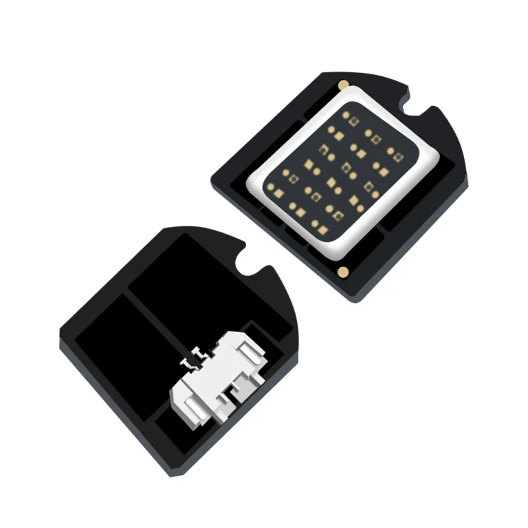
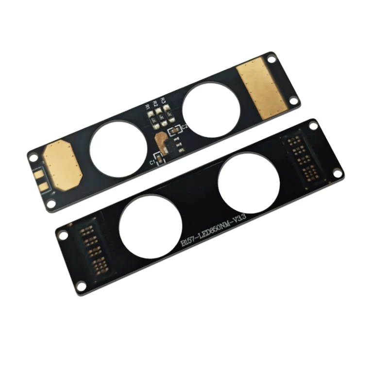
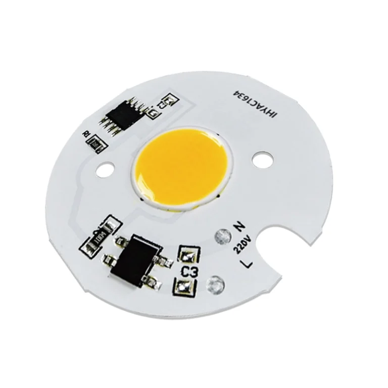
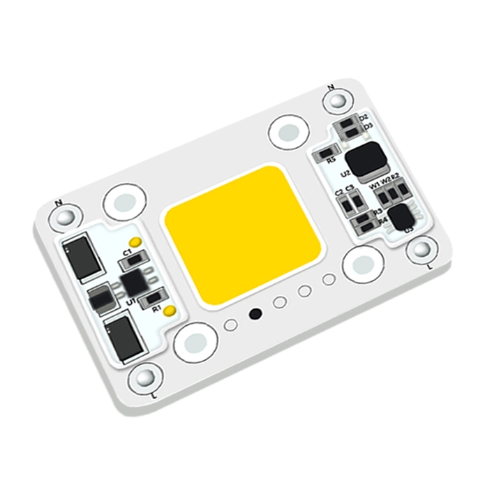
Start with the available power source and control method, then consider the emitting surface, PCB geometry, and required integration level. Shenzhen IHY Lighting Co., Ltd. publicly groups its module products into DC, AC, UV/IR, and cinematic or studio lighting categories, with examples using rigid and flexible substrates, connectors, different emitting shapes, and multiple electrical configurations.
Choose the Electrical Architecture
A constant current module is evaluated against the driver’s output current and voltage window. A regulated constant voltage module may suit equipment with a defined DC bus, but its accepted input range must be verified. A printed “12V” or “24V” label does not show whether the value is a regulated input, nominal operating point, or LED forward voltage condition.
AC or integrated modules can reduce external components, but buyers still need to confirm input limits, protection, dimming, thermal conditions, and service strategy. Multichannel modules require separate checks for each channel. Zhaga’s interface guidance likewise treats driver-module compatibility as a comparison of voltage, current, and power capabilities rather than wattage alone.
Choose the Light Source and PCB Architecture
COB modules are often considered when a compact light emitting surface(LES), continuous appearance, or concentrated optical system is required. SMD arrays may offer more freedom for distributed illumination or separately controlled channels. The decision should follow the final optical and thermal system, not package terminology alone. A deeper comparison belongs in COB LED vs SMD LED.
Rigid PCBs suit products with a stable mounting surface and defined heat path. Flexible or custom shaped boards can help with curved housings, narrow cavities, rings, or unusual wire exits. They are not automatically suitable for high load applications; bending, mechanical support, conductor routing, and heat transfer still require review.
Check the Four Compatibility Interfaces
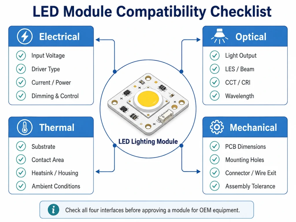
A module should not be approved until its electrical, optical, thermal, and mechanical interfaces have been checked together.
| Interface | What to Compare | Common Failure If Ignored |
| Electrical | Input type, voltage, current, power, control, polarity | No start, flicker, or overdrive |
| Optical | Output target, LES, beam, focal position, color, or wavelength | Low intensity, hot spots, or incorrect beam |
| Thermal | Power density, substrate, contact area, housing, ambient conditions | Excess temperature or unstable output |
| Mechanical | Outline, thickness, holes, connector, wire exit, tolerances | Assembly conflict, poor contact, or misalignment |
Verify the Electrical and Control Interface
For constant current systems, compare the driver’s current rating and output voltage range with the module requirements. For constant voltage systems, confirm where regulation is provided and whether the module accepts the full supply range. Also check startup behavior, polarity, connector rating, dimming method, channel count, and control interface.
Two same wattage modules may draw different current, operate at different forward voltages, or require different controls. Test samples with the intended production driver, wiring, connector, and controller. A laboratory supply may show that the LEDs illuminate, but it does not prove compatibility with the final equipment.
Verify the Optical Interface
Define the requirement in terms that match the application. General illumination may use lumens and illuminance. A focused beam may depend more on candela, working distance, beam profile, and LES position. UV and IR products may require wavelength and radiant output specifications.
Compare LES dimensions and location with the lens, reflector, light guide, or diffuser. Equal lumen output can produce different center intensity or uniformity when the emitting area changes. Color critical products should define CCT, CRI, R9, color tolerance, or channel requirements where relevant. Approve the optics inside the intended housing at the production working distance.
Verify the Thermal and Mechanical Interfaces
Substrate material alone does not determine operating temperature. Review power density, contact area, surface flatness, interface material, heatsink or housing, airflow, ambient temperature, and duty cycle. A module that performs well on an open bench may run much hotter, or even fail once installed inside a sealed enclosure.
Mechanical review should compare the PCB outline, thickness, mounting holes, connector position, wire exit direction, emitting surface height, focal position, and thermal contact surface. For replacement projects, compare drawings rather than relying on a photo or nominal dimensions. Prototype approval should include assembly sequence and tolerance checks.
Decide Between a Standard, Replacement, or Custom Module
A standard product is usually the lower risk choice when the input, driver, outline, mounting method, LES, optical output, connector, and thermal path already fit the equipment. Buyers can review available LED modules for OEM equipment before requesting a new board.
Custom development becomes reasonable when a critical interface cannot be matched. Typical triggers include a restricted cavity, special PCB shape, unusual voltage or current distribution, flexible construction, a defined LES, UV/IR or multichannel spectrum, integrated control components, or reduced wiring and assembly. IHY Lighting’s published solution scope includes AC, DC, COB, SMD, flexible, integrated, UV, IR, and application-specific configurations.
For replacement purchasing, equal wattage is not enough. Verify voltage, current, driver type, output, spectrum, LES position, dimensions, holes, connector, heat transfer area, and operating conditions. If the old module lacks reliable documentation, collect photos, measurements, wiring information, driver labels, and a working sample where available. A replacement may require changes to the driver, optics, mounting, or housing.
Prevent Integration Failures Before Mass Production
Prototype failures should be traced to the relevant interface. Flicker often points to driver, dimming, wiring, or control incompatibility. Low center intensity may result from an LES and lens mismatch. Hot spots can be caused by source spacing or insufficient diffuser distance. Overheating may indicate poor thermal contact, excessive power density, unsuitable housing conditions, or an incomplete heat path.
Test the module in the final equipment configuration with the planned driver, optics, heatsink, interface material, enclosure, connector, wiring, control mode, duty cycle, and ambient conditions. Establish written acceptance criteria for electrical operation, temperature, output, beam, color or spectrum, assembly, startup, and dimming. A prototype that merely lights up is not production approved.
Prepare an RFQ and Evaluate an OEM LED Module Supplier
A quote ready request should identify the application, available space, target optical result, power architecture, operating environment, and project stage. Useful inputs include a drawing or sample, maximum dimensions, mounting and connector requirements, driver data, target output and beam, LES limits, CCT or wavelength, thermal information, prototype quantity, and estimated demand.
A supplier should be able to define the proposed input, board construction, connection method, optical conditions, thermal assumptions, dimensions, and test conditions. Request controlled drawings, revision identification, sample acceptance criteria, and a process for communicating engineering changes. Warning signs include recommendations based only on wattage, unclear input limits, missing drawings, or test data without stated conditions.
Shenzhen IHY Lighting develops COB LEDs, LED modules, and application solutions for OEM and ODM projects. Its confirmed customization scope includes custom PCB geometry, optical and spectral configurations, voltage and current adaptation, multiple substrate options, and integration of driver, control, connector, or related components where required. Projects not served by a standard module can be directed to custom LED module solutions for application specific review.
Conclusion
Selecting an LED lighting module is an interface matching decision, not a wattage comparison. Define the supply boundary, select the architecture, verify electrical, optical, thermal, and mechanical compatibility, and test the module inside the intended equipment. Before requesting a quotation, prepare the application, drawings, dimensions, driver information, optical target, operating conditions, sample or failure photos, and expected quantity.
To discuss a standard, replacement, or custom project, contact IHY Lighting with the available technical information. The first objective should be to establish compatibility and identify missing data before samples or production specifications are approved.
FAQs
Does an LED lighting module always need a driver?
A basic LED module normally requires a compatible driver. Some regulated DC, AC, or integrated modules include current control or power components. Confirm the input specification and connection diagram rather than relying on the product name.
Can a 12V LED module connect directly to a 12V power supply?
Only when the module is specified for regulated 12V input across the expected supply range. A 12V marking may instead describe a nominal operating point or forward voltage.
Can a same wattage LED module replace the existing module?
Not automatically. Compare voltage, current, driver type, output, LES, color or spectrum, dimensions, holes, connector, and thermal interface. The replacement may also require changes to the driver, optics, or mounting.
How can an overheating LED module be prevented?
Check power density, contact area, interface material, heatsink or housing, airflow, ambient temperature, and duty cycle. Measure temperature in the final enclosure under the intended operating condition.
What information is needed for a custom LED module quotation?
Provide the application, dimensions, drawing or sample, input and driver information, target output, beam or wavelength, thermal environment, connector and mounting requirements, prototype quantity, and expected production demand.