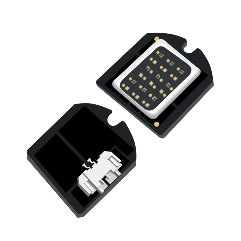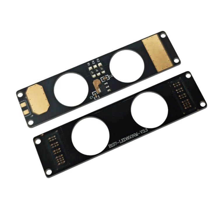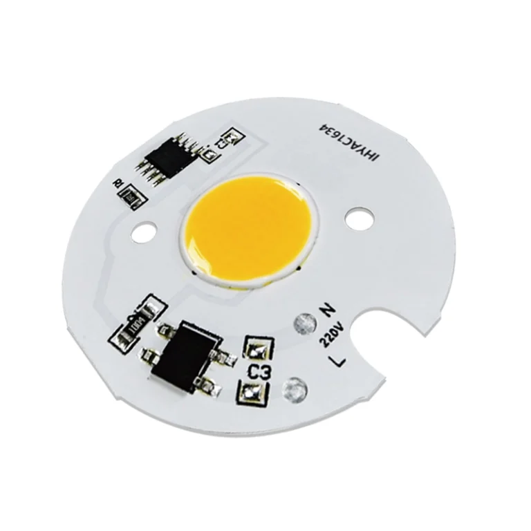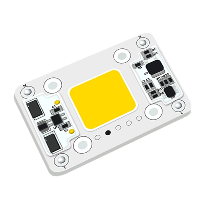




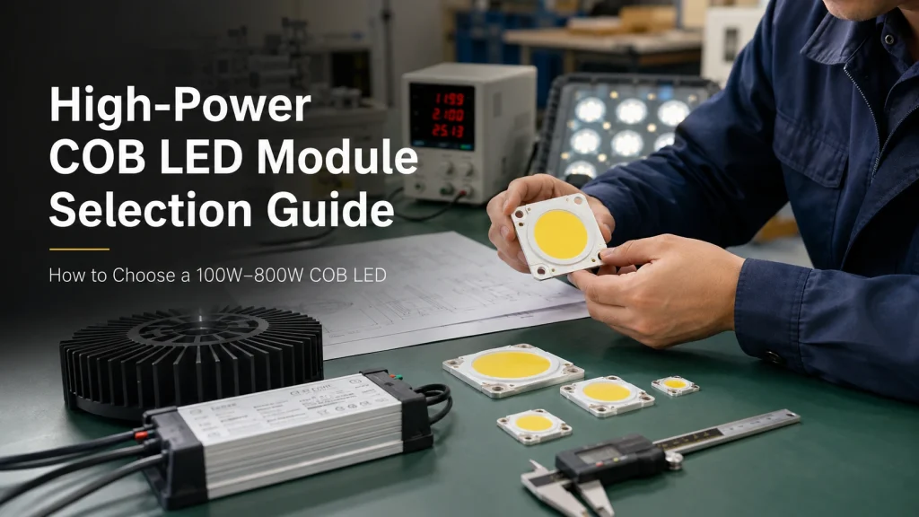
Selecting a high power COB LED module is not a simple matter of choosing the highest wattage.
For an OEM lighting project, the module must work seamlessly with the driver, heat sink , optics, enclosure, controls, and operating environment.
Rated power alone does not show if a 100W or 800W COB LED can produce the needed light stay within safe temperatures, or fit an existing fixture. The practical task is to convert the application into measurable electrical, optical, thermal, and mechanical requirements before asking for samples.
Start With the OEM Application, Not the Wattage
Translate the Lighting Target Into COB LED Requirements
A single high wattage COB LED often suits products that need a compact, intense source behind a reflector, lens, or projection system. It may be unsuitable when the product needs a broad luminous surface or independent control across several zones.
Do not translate “the fixture must be brighter” directly into a wattage increase. First check if the problem is from low luminous flux, weak center intensity, an unsuitable beam angle, optical losses, high temperature, or insufficient drive current. The high power COB LED module range is a useful starting point, but each choice still needs to be checked as part of the whole lighting system.
Decide Whether the 100W–800W Range Fits the Project
When superior optical designs, better heat cooling or several lower power modules can’t meet the goal. Then a high power COB LED solution is needed , When comparing 100W,200W,500W or 800W COB LED options, check forward voltage, rated current, light-emitting surface (LES), substrate dimensions, cooling method, and optical compatibility. An ultra high power module is not a good idea when the enclosure cannot support the required heat sink, airflow, insulation distance, or mounting pressure.
Match the COB LED to the Driver and Electrical Architecture
Driver mismatch can cause unstable output, failed startup, overheating, or operation outside the intended rating. LED array electrical guidance treats the relationship between forward voltage, drive current, and light output as a primary design input.
Match Forward Voltage, Drive Current, and Driver Output Range
A high power COB LED normally requires a compatible constant current driver. The current setting should match the intended operating current, while the output-voltage window must cover the COB LED forward voltage across temperature and production variation.
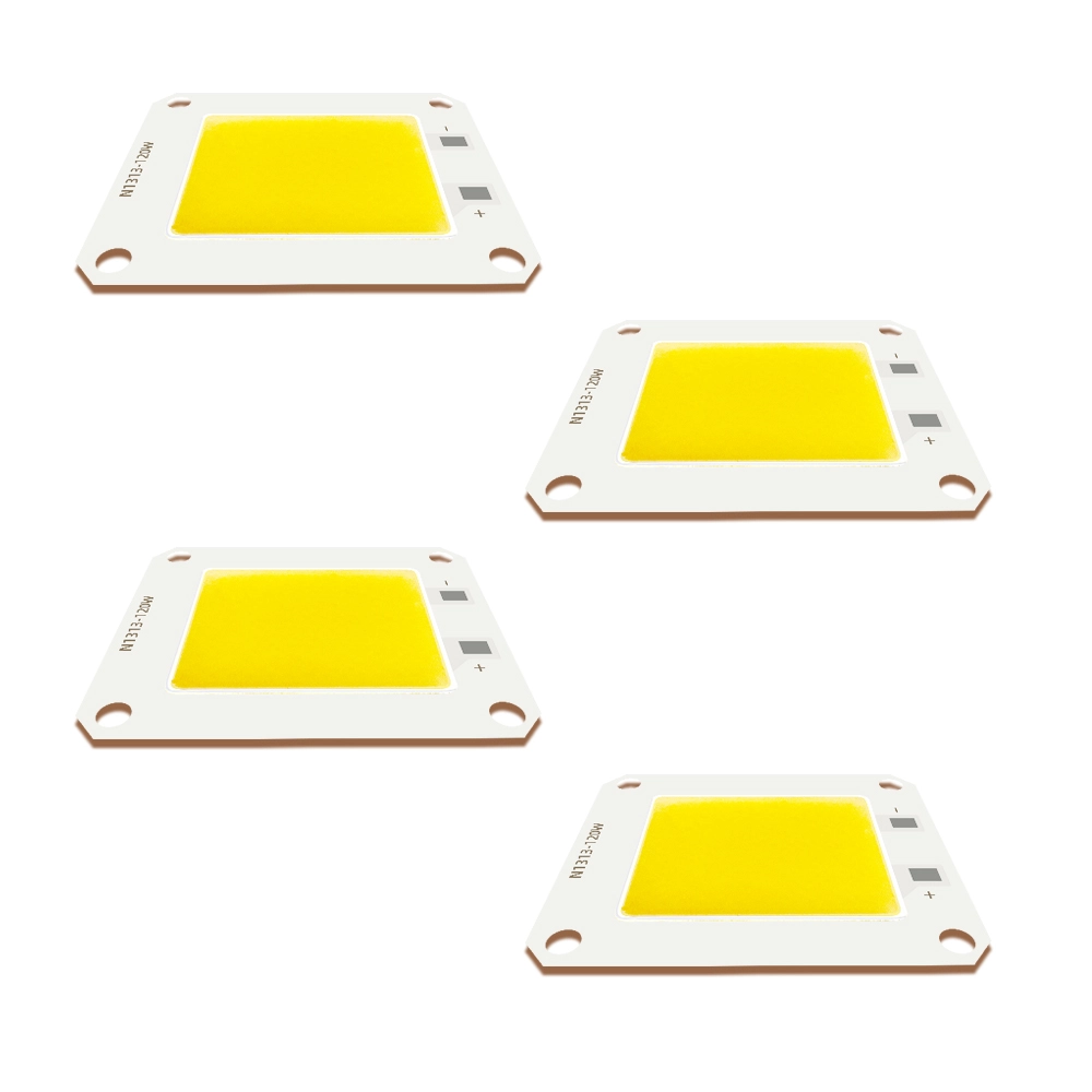
Two modules with the same nominal wattage may require completely different drivers. Before buying check rated typical and max forward voltage, channel setup, dimming method, connector type and protection needs. Taking a high power 78V 120W COB LED module as an example (such as the N1313 model usa a 54×46×2 mm aluminum substrate), its nominal specifications are 78V and 1.5A. Based on the calculated actual electrical power (P = Vf × If = 78V × 1.5A = 117W), it is classified as a 120W class module. This highlights the critical engineering practice: OEMs must evaluate true operating wattage based on actual Vf xIf limits under stabilized temperature rather than relying solely on nominal marketing labels prior to driver selection.
Choose Between High Voltage and High Current Designs
A high voltage, lower current COB LED reduces conductor current and transmission I²R voltage drop. However, when the forward voltage exceeds the 60V DC threshold for Safety Extra Low Voltage (SELV)—such as in a 78V architecture—the system no longer qualifies as SELV. This requires strict adherence to higher insulation standards, increased creepage and clearance distances, and compliance with more stringent shock protection regulations (such as IEC 61347 or non-SELV/Class 1 requirements), which ultimately drives up driver costs and complicates enclosure isolation design.
Conversely, low voltage, high current COB LEDs (operating below 60V DC) are ideal for SELV or battery-powered systems. However, they demand thicker wire gauges, wider PCB traces, robust high-current connectors, and tight control over contact resistance.
The optimal choice depends on factors such as the power supply, driver availability, cable length, control method, enclosure design, and safety requirements. When issuing a request for quotation (RFQ), be sure to clarify whether the specified current refers to the total module current or the current per channel.
Before ordering samples, please resolve any potential discrepancies between voltage, current, and rated power.
Select the LES, Optics, and Light Quality Specifications
Even if a COB LED module meets electrical rating specifications, failure can still occur if its LES, optical positioning, or color characteristics are incompatible with the luminaire. Since secondary optical components—such as reflectors, lenses, and collimators alter the light distribution of the source, optical compatibility should be considered during the initial selection phase.
Choose the LES for the Required Beam
According to the physical principles of optical etendue conservation, a smaller light emitting surface (LES) allows secondary optics (reflectors, TIR lenses) to capture and focus light into a tighter beam angle with significantly higher Center Beam Candlepower (CBCP) using compact optical apertures. Conversely, a larger LES increases system etendue, producing broader emission that requires substantially larger optic diameters to achieve narrow beam control. The correct choice depends on reflector aperture, focal position, lens geometry, working distance, and target beam distribution.
For a replacement, record the original LES dimensions, mounting relationship, and distance to the optical reference point. A module with the same outer dimensions may still produce a different beam if the LES changes. Always request a mechanical drawing, LES dimensions, CCT, CRI, and relevant photometric or spectral information.
Validate Thermal, Substrate, and Mechanical Compatibility
High power COB LED thermal management must be treated as a complete path from the LED junction through the substrate, thermal interface material (TIM), heat sink, enclosure, and surrounding air. Industry guidance recommends testing under representative conditions and measuring case temperature after thermal stabilization.
Check the Complete Thermal Path
Rated power does not guarantee that the finished fixture can operate continuously at that power level. The acceptable operating point depends on condition temperature, system thermal resistance, TIM quality, heatsink performance, airflow, and nearby heat sources.
Short bench tests are insufficient. Build a representative assembly with the intended mounting method and thermal interface material, then test it inside the actual or equivalent enclosure until temperature stabilizes. Confirm the case temperature measurement point and compare results with applicable limits.
Aluminum and copper substrates must be evaluated within the context of the entire thermal stack. For ultra high power COB modules (e.g., 300W–800W), the extremely high heat flux makes copper substrates—particularly those with a thermoelectric separation design—advantageous; their superior thermal conductivity rapidly reduces lateral thermal resistance, thereby preventing localized chip overheating. However, the overall thermal dissipation limit of the system remains constrained by the heat sink’s thermal capacity and the efficiency of heat exchange with the ambient air.
Confirm Mechanical Fit Before Ordering Samples
Carefully review the PCB specs—including dimensions, thickness, mounting hole layout, contact pads, connector orientation, polarity, and LES positioning. Proper alignment between the optical center and the reflector or lens is critical, as is choosing a mounting technique that achieves reliable thermal coupling without stressing the COB LED.
Use a controlled drawing rather than product photographs. Reliable electrical connection and efficient heat sink contact are both necessary during LED array assembly.
Prevent Selection and Replacement Failures
A replacement selected only by wattage or outside dimensions may overload the driver, run too hot, shift the beam, or fail to align with the optics.
| Compatibility area | Confirm before approval |
| Electrical | Forward-voltage range (Vf min/max), rated current (If), driver mode (constant current), dimming protocol, channel structure, SELV compliance (voltage threshold), connectors. |
| Thermal | Junction to case thermal resistance (Rth_j-c), substrate material (Aluminum vs. Direct Thermal Path Copper), case temperature point (Tc), TIM selection, heat sink capacity. |
| Mechanical | PCB outline dimensions, PCB thickness, mounting hole location and diameters, terminal pad layout, LES central positioning, structural clearance. |
| Optical | Light Emitting Surface (LES) diameter and shape, etendue match, luminous flux target, CCT, CRI/SDCM, reflector/lens aperture and focal alignment. |
Common mistakes include selecting by wattage alone, accepting incomplete electrical data, treating optics as a downstream task, approving samples before thermal stabilization, and relying on marketing claims instead of measurable acceptance criteria. When product fields conflict, request a revised specification or circuit explanation.
Decide Between a Standard and Custom High Power COB LED Module
A standard module is appropriate when its electrical rating, LES, board dimensions, optical characteristics, and thermal interface fit without major redesign. Customization becomes relevant when the project requires a nonstandard voltage current combination, board shape, LES, mounting pattern, color specification, channel structure, or integration with a driver or optical component.
Compare the risk of modifying the fixture with the cost of developing a custom module, including engineering changes, qualification work, and future replacement needs.
Shenzhen IHY Lighting Co., Ltd. presents itself as a custom COB LED light engine manufacturer offering mid-to-high-end COB LED products alongside integrated driver, optical, and application-specific solutions. Final requirements should still be documented through drawings and approved specifications.
Evaluate Suppliers and Prepare a High Power COB LED RFQ
A suitable supplier should explain how the proposed COB LED fits the project’s driver, thermal path, optical system, and mechanical envelope. Request the current datasheet, mechanical drawing, electrical configuration, LES dimensions, substrate details, relevant thermal information, color specification, and sample acceptance conditions. Check that voltage, current, and power values are consistent. For multichannel products, request enough detail to understand the driver architecture.
A useful RFQ should include the COB LED application,PCB size, power, voltage, brightness, color rendering index (CRI), ambient temperature, cooling method, dimming requirements, sample quantity, and expected production volume. For replacement work, attach the original specification, photographs, measured dimensions, driver label, and a description of the failure.
IHY Lighting can be approached through submit a high-power COB LED inquiry after these inputs are assembled. Complete project information helps determine whether a standard product, or a custom configuration deserves further evaluation.
Conclusion
A reliable high power COB LED selection starts with the application and ends with a tested system. Wattage defines a search range, but the decision depends on forward voltage, drive current, driver headroom, SELV safety compliance, LES, optics, thermal resistance, mounting, color requirements, and operating conditions.
Before requesting a quote, please prepare the following information : application description, target luminous flux, optoelectronic parameters, dimensional drawing, thermal management method, control requirements, sample quantity, and expected volume.Then Shenzhen IHY Lighting Co., Ltd. will check whether a standard or custom high power COB LED configuration is more suitable.
Frequently Asked Questions (FAQ)
Is a higher wattage COB LED necessarily brighter?
No. Usable output also depends on efficacy (lm/W), drive current, operating junction temperature, LES size, optical system efficiency, and the required beam distribution.
Weather two COB LEDs with the same wattage can use the same driver?
Not necessarily. Compare rated current, forward-voltage range across temperature extremes, channel structure, dimming protocol, and SELV voltage limits.
Can a COB LED be replaced by another module with the same dimensions?
Only after electrical, thermal, mechanical, and optical compatibility are confirmed. Matching outer dimensions does not guarantee the same forward voltage, LES position, beam angle, or thermal impedance.
What information is needed for a custom high power COB LED?
Provide the application, optical target (beam angle/CBCP), voltage/current limits, SELV restrictions, control method, LES requirement, board dimensions, mounting details, thermal conditions, color specification, sample quantity, and expected volume.