



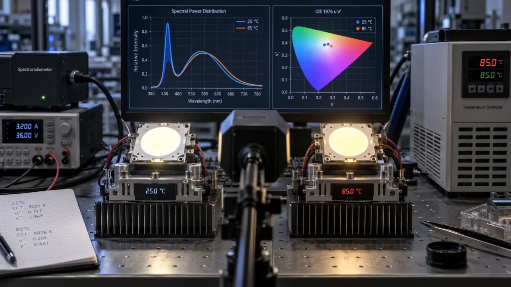
A COB LED that meets its color target at 25°C may move to a different chromaticity point at operating temperature. The shift can come from temperature
dependent changes in the blue pump, phosphor conversion, encapsulant, drive current, and thermal path. CCT alone may hide that movement. A useful 25°C-to-85°C evaluation records chromaticity coordinates and interprets three quantities: Δu’v’ for total movement, Duv for tint relative to the Planckian locus, and SDCM for position within a color tolerance region.
Define which temperature is controlled, keep electrical and optical conditions consistent, allow the COB to stabilize, and compare the same metrics at every setpoint. Otherwise, the temperature and color results cannot be connected reliably.
Why COB LED Color Shifts as Temperature Rises
A white COB combines many LED dies with a phosphor conversion system. As junction temperature rises, the blue emission spectrum and phosphor conversion efficiency can change at different rates. The resulting spectral balance may move the measured chromaticity even when input current remains nominally constant. Optical materials and package construction can add further temperature dependence.
The magnitude and direction are product specific. One COB may move mainly along the CCT direction, another across the green magenta axis, and another along a curved path. Drive current, thermal resistance, phosphor formulation, optics, and measurement geometry influence the result. The U.S. Department of Energy’s LED color stability research also identifies operating temperature and current as important influences.
An 85°C chamber ambient, 85°C case temperature, and 85°C junction temperature are not equivalent. The report should name the controlled temperature and record case temperature at the manufacturer’s defined point. Estimate junction temperature only with applicable thermal data. IHY Lighting’s guide to COB LED thermal management explains why case, ambient, and junction temperatures must remain separate.
What Δu’v’, Duv, and SDCM Actually Tell You
These metrics describe different relationships. They should be reported together rather than treated as interchangeable limits.
Δu’v’ Measures Total Chromaticity Movement
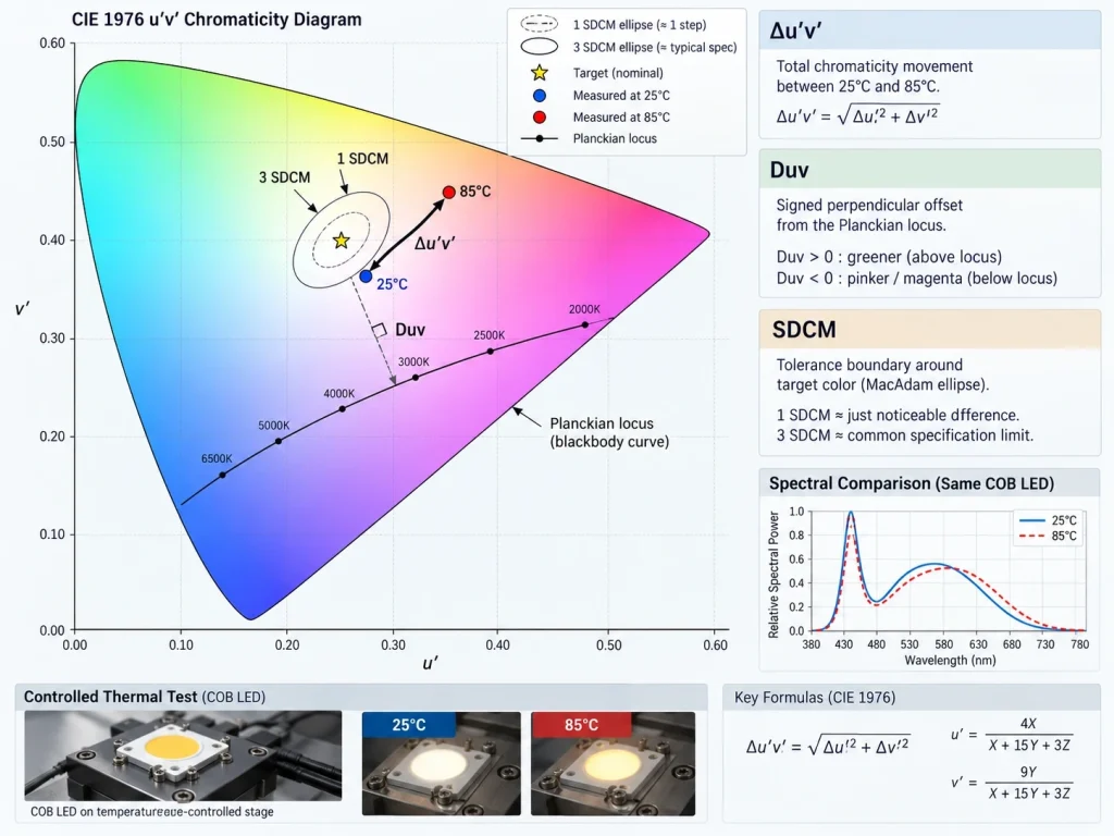
In the CIE 1976 uniform chromaticity scale, a source is located by u’ and v’. The point to point difference between a baseline and a hot measurement can be expressed as:
Δu’v’ = √[(u’₂ – u’₁)² + (v’₂ – v’₁)²]
This unsigned distance shows how far the color point moved, but not its direction. Retain the coordinate pairs or a chromaticity plot because two COBs can have the same Δu’v’ while moving in different directions.
Duv Shows Tint Relative to the Planckian Locus
Duv is a signed distance from the Planckian, or blackbody, locus at the source’s CCT. In normal white light interpretation, positive Duv lies above the locus and tends toward a greener tint; negative Duv lies below it and tends toward a pinker or more magenta tint. Duv is especially useful when a small CCT change produces an unacceptable tint change.
Duv is not the same as the Δu’v’ distance between 25°C and 85°C. A COB can move largely along the locus, producing measurable Δu’v’ with little change in Duv. It can also cross the locus, changing the sign of Duv even when the total movement is modest. Record both Duv at each setpoint and ΔDuv from the 25°C baseline.
SDCM Describes Tolerance Around a Target Color
SDCM, commonly discussed through MacAdam ellipses, expresses how far a chromaticity point sits from a target region in perceptual step units. A lower step specification defines a tighter color tolerance region. Because the ellipses change in size and orientation across the chromaticity diagram, SDCM does not have a universal one to one conversion to Δu’v’ or Duv.
SDCM shows whether a hot state color point remains inside the agreed bin or application tolerance. It does not replace the coordinate path. Retain the target chromaticity, ellipse definition, baseline point, hot point, and measurement uncertainty.
A Repeatable 25°C to 85°C Test Method
A controlled test controls thermal, electrical, and optical variables that can imitate color shift.
- Define the temperature basis. State whether 25°C and 85°C refer to ambient, case, or another controlled reference. Identify the case measurement point and the method used to estimate junction temperature, if required.
- Fix the operating point. Use the intended driver, dimming state, thermal interface, mounting, heatsink, optics, and enclosure. Record actual current and voltage at every setpoint.
- Establish a stabilized baseline. At 25°C, wait until both thermal readings and photometric values stop changing materially. Measure spectral power distribution, CCT, x and y, u’ and v’, Duv, flux, and relevant colorquality metrics.
- Increase temperature in defined steps. Intermediate points such as 40°C, 55°C, and 70°C can reveal nonlinearity that an endpointonly test would miss. Stabilize before each measurement and use the same instrument geometry.
- Measure at 85°C. Repeat the complete optical and electrical record. Calculate Δu’v’ from the baseline, calculate ΔDuv, and plot the coordinate path against the agreed SDCM boundary.
- Return to 25°C. A recovery measurement helps distinguish reversible temperature behavior from permanent drift or damage caused during the test.
- Test more than one unit. Compare units and production lots when color matching matters. A single sample cannot characterize manufacturing variation.
Instrument calibration, chamber uniformity, stray light, self heating, stabilization time, and fixture repositioning contribute uncertainty. State these controls so teams can compare supplier data on the same basis.
Turn the Measurements into an Acceptance Specification
Avoid a requirement such as “no visible color change from 25°C to 85°C.” It is subjective and omits the thermal reference, initial bin, observer conditions, and measurement method. Use testable requirements instead:
- maximum pointto point Δu’v’ from the 25°C baseline;
- permitted Duv range at each temperature and maximum ΔDuv;
- required SDCM boundary relative to the nominated target;
- current, duty cycle, stabilization rule, optics, and temperature reference;
- allowed measurement uncertainty and sampling plan; and
- recovery requirement after returning to 25°C.
Set limits from the application’s visual sensitivity and risk. Museum, retail, studio, medical, machine vision, and multi emitter products may need different controls. Adjacent COBs may require tighter matching than one isolated source. Provide the supplier with the viewing geometry, target CCT, optics, and emitter arrangement before setting thresholds.
What to Request from a COB LED Supplier
For an RFQ or sample approval, send the target CCT and Duv, color tolerance, operating current, thermal reference, maximum temperatures, duty cycle, heatsink or enclosure details, optics, dimensions, drawings, quantity, and application. Ask for the initial bin, test current, stabilization method, instrument geometry, sample count, and full 25°C-to-85°C chromaticity data rather than one CCT value.
IHY Lighting offers high power COB light engines and custom COB development for OEM projects. Product suitability and color shift limits should still be confirmed against a project specific specification and representative samples. If temperature dependent color consistency is critical, include the acceptance matrix in the drawing or quality agreement before production approval.
Conclusion
COB LED color shift from 25°C to 85°C cannot be judged from CCT alone. Δu’v’ quantifies total chromaticity movement, Duv shows the tint relationship to the Planckian locus, and SDCM tests the result against a perceptual tolerance region. A controlled, stabilized, multi point test with a return to baseline check turns those metrics into useful engineering evidence. IHY Lighting can discuss your COB LED requirements when the RFQ includes the electrical, thermal, optical, mechanical, and acceptance conditions needed for a fit check.
FAQs
Is Δu’v’ the same as Duv?
No. Δu’v’ is the unsigned distance between two points in the CIE 1976 u’v’ diagram. Duv is a signed distance from the Planckian locus and indicates movement toward green or magenta.
Can CCT stay stable while Duv changes?
Yes. A chromaticity point can move across the Planckian locus with only a small CCT change. That is why CCT and Duv should be recorded together.
Does three SDCM equal a fixed Δu’v’ value?
No. MacAdam ellipses vary with chromaticity and direction, so there is no universal conversion. Use the specified target ellipse or tolerance model for the relevant CCT.
Should 85°C mean ambient or case temperature?
The specification must say which one. Ambient, case, and junction temperatures describe different conditions and cannot be substituted for one another.