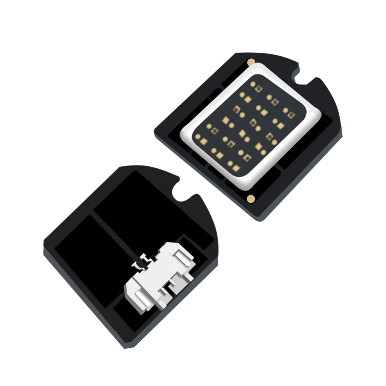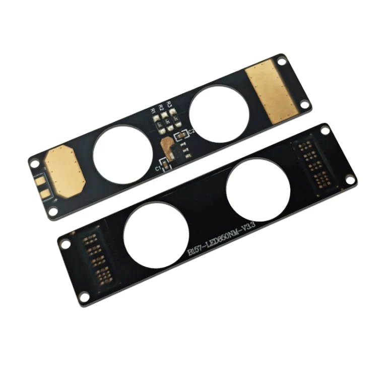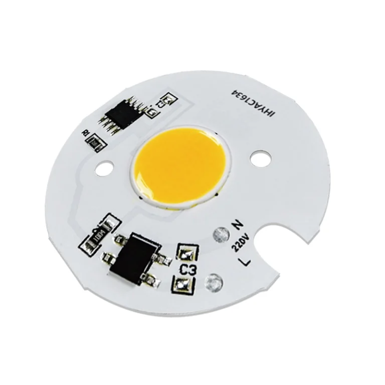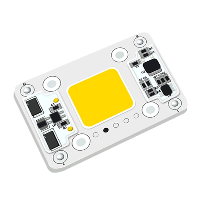




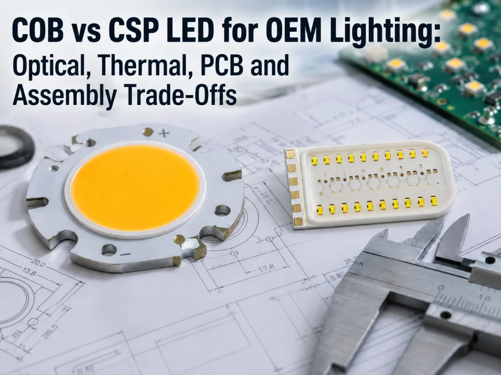
For an OEM engineer comparing COB vs CSP LED, the useful question is not which technology is universally better. The real question is which architecture fits the product’s optical system, thermal path, PCB layout, assembly process, and total production cost.
COB can simplify designs that need a compact, unified light emitting surface and a defined module-level interface. CSP can provide greater freedom when individual emitters need to be positioned directly on a PCB through an SMT-oriented assembly process. Neither advantage exists in isolation. A package that looks attractive on a datasheet can create problems if its source geometry, operating conditions, manufacturing requirements, or thermal path do not match the finished product.
For OEM lighting, the selection should therefore start with system requirements rather than package terminology.
COB vs CSP LED: Which One Fits Your OEM Lighting Design?
A chip-on-board design integrates multiple LED dies on a shared substrate to form a concentrated emitting area. Chip scale packages, by comparison, are compact individual LED packages that can be placed on a circuit board according to the required layout.
That distinction affects much more than physical size.
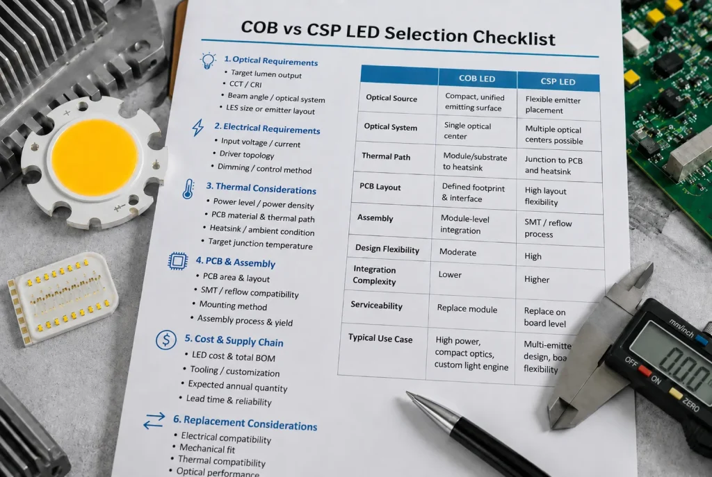
| Design Requirement | COB May Be a Better Starting Point When… | CSP May Be a Better Starting Point When… |
| Optical source | A compact, unified emitting surface is required | Emitters need independent positioning |
| PCB architecture | A defined light-source module simplifies integration | Board-level layout flexibility is important |
| Manufacturing | The OEM prefers module-level integration | Existing production is suited to SMT/reflow assembly |
| Optics | The lens or reflector is designed around one source | The optical system works with multiple source positions |
| Mechanical design | A custom substrate or emitting shape is useful | Small individual package footprints help the layout |
| Service strategy | Replacing a complete light-source module is acceptable | Board-level component architecture is preferred |
Choose by System Requirements, Not by Package Name
COB or CSP LED selection becomes easier after the design team defines what the light source must actually do. Useful inputs include target optical output, CCT and CRI, available PCB area, desired beam, operating voltage and current, ambient conditions, heatsink limitations, and production method.
This prevents a common sourcing mistake: comparing LEDs by wattage, efficacy, or package size before checking whether the optical and mechanical interfaces are compatible.
For projects using a compact emitting area or a custom light-source geometry, reviewing available custom COB LED solutions early can help determine whether a module level architecture fits the product. IHYLight publicly offers COB LED categories covering different light-source structures and application requirements.
Optical Trade-Offs: LES, Beam Control, and Light Uniformity
When engineers search for COB vs CSP optical design or COB vs CSP LES differences, they are usually trying to answer a practical question: will the new light source work with the intended lens, reflector, diffuser, or light guide?
The answer depends heavily on source geometry.
When a Compact LES Gives COB an Advantage
A COB architecture can be attractive when the optical system is built around one concentrated light emitting surface. Examples include designs where a reflector or lens expects a defined optical center, or where the mechanical envelope leaves little room for a distributed LED array.
The important specification is not simply lumen output. Engineers should examine LES dimensions, emitting shape, optical center, required beam angle, working distance, and the dimensions of the secondary optics.
A COB with sufficient output can still be unsuitable if its LES is too large for an existing reflector. The result may be a wider beam, reduced center intensity, unwanted spill, or lower optical efficiency. For replacement and redesign projects, the existing optical geometry should therefore be documented before requesting an alternative light source.
When CSP Layout Flexibility Matters More
CSP becomes more attractive when individual emitter placement is part of the product architecture. An engineer may need LEDs distributed over a board, arranged around another component, divided into separate optical channels, or positioned to match several lenses.
In these cases, package footprint, placement tolerance, emitter pitch, PCB geometry, and optical consistency deserve more attention than the simple question of COB vs CSP LED efficiency.
CSP is less compelling when the product depends on one tightly controlled emitting area and the optical system has already been developed around a specific LES. Changing package architecture at that stage can turn a component substitution into a broader optical redesign.
COB vs CSP Thermal Management: Why Package Type Is Not Enough
Questions such as “which has better heat dissipation, COB or CSP?” appear simple, but package type alone does not determine thermal performance.
Heat must travel from the LED junction through the package or substrate, PCB or interface material, mechanical mounting system, and heatsink before reaching the surrounding environment. A weakness anywhere along that path can raise junction temperature.
Compare Junction Temperature and the Complete Thermal Path
For high-power lighting, compact equipment, or products operating at elevated ambient temperatures, designers should review junction temperature limits, thermal resistance data, power density, PCB construction, thermal interface material, mounting pressure, and heatsink capacity.
Test conditions matter as well. A thermal resistance figure from one package cannot be compared meaningfully with another unless the measurement boundaries and operating conditions are understood.
A safer development process is to calculate the expected thermal path, build a representative prototype, and validate performance under the product’s realistic worst-case operating condition. This is especially important when enclosure size, airflow, or heatsink volume is restricted.
The same system approach applies beyond the LED package. The LED light engine design guide provides a useful next step for engineers evaluating the interaction between the light source, driver, optics, PCB, and thermal structure.
Compare Efficiency Under Equivalent Conditions
Is CSP LED more efficient than COB? A useful comparison requires more information than two headline lm/W figures.
CCT, CRI, drive current, junction temperature, binning, and optical losses can all affect measured performance. Comparing a lower CRI device operated under favorable conditions with a higher CRI alternative at a different current does not isolate the effect of package architecture.
OEM teams should request the operating conditions behind performance data and compare the complete light engine where possible. A package-level advantage may narrow after driver losses, optical losses, and thermal behavior are included.
PCB and Assembly Trade Offs
COB vs CSP PCB selection can influence manufacturing cost as much as optical performance. The relevant question is whether the OEM wants to integrate individual packages at board level or integrate a more defined light-source module into the product.
CSP for Board Level SMT Integration
CSP can suit manufacturers whose PCB architecture and production process are designed around compact surface-mounted components. It can also help when individual emitter placement is important.
Before specifying CSP, the engineering and sourcing teams should confirm package dimensions, recommended land pattern, placement tolerances, reflow requirements, board thermal design, handling requirements, and expected manufacturing process.
A low component price does not necessarily produce a low assembled cost. PCB complexity, placement accuracy, yield, inspection, rework, and optical alignment can change the economics. These factors become particularly important when evaluating high volume production rather than a laboratory prototype.
COB for Module-Level Light-Source Integration
COB may reduce integration work when the OEM wants a light source with a defined substrate, emitting area, electrical configuration, and mechanical interface.
This approach can be useful when the product team wants to treat the light source as a subsystem rather than manage multiple individual emitters. However, the purchasing team still needs to verify substrate dimensions, mounting method, electrical pads or connectors, operating voltage and current, thermal interface, and optical requirements.
Total assembled BOM is a more useful purchasing metric than LED unit price. PCB cost, SMT operations, optics, thermal hardware, assembly labor, inspection, and redesign risk should all be considered.
Engineers comparing other package architectures can also review the existing COB vs SMD LED selection guide without expanding the current article into a separate COB-versus-SMD discussion.
Can CSP Replace an Existing COB LED?
“Can CSP replace COB LED?” is often a redesign question rather than a component-selection question. The existing COB may be affected by supply changes, cost pressure, mechanical revisions, or new performance targets.
A CSP alternative should not be selected only because its wattage or nominal output appears similar.
Check Four Types of Compatibility Before Replacement
First, check electrical compatibility. The new architecture must work with the required voltage, current, driver topology, and control method.
Second, review thermal compatibility. Changing the emitter architecture can change heat distribution across the PCB and the requirements placed on the heatsink.
Third, check mechanical compatibility, including available board area, mounting points, component clearance, and connector position.
Finally, verify optical compatibility. LES dimensions, source positions, beam distribution, lenses, reflectors, and diffusers may all be affected.
A replacement that passes the electrical check can still fail thermal or optical validation. Prototype testing should therefore be part of a COB-to-CSP redesign before production documentation is released.
How OEM Buyers Should Compare COB and CSP Suppliers
Supplier selection becomes important once the architecture moves from research into prototyping or sourcing. A qualified supplier should be able to discuss the light source in the context of optical, electrical, thermal, PCB, and mechanical requirements rather than treating package type as the only design decision.
Ask for Design Evidence, Not Just Headline Specifications
An RFQ should identify target output, CCT and CRI, LES or package constraints, operating voltage and current, available PCB space, ambient environment, thermal limitations, optical system, mechanical envelope, expected quantity, and any existing light source being replaced.
Datasheet values should be checked for their test conditions and tolerances. For custom work, engineers should also establish which requirements are fixed and which can change during development.
IHYLight positions its business around COB LEDs, LED modules, and integrated light-engine solutions rather than only individual standard components. The IHYLight OEM lighting solutions overview can help buyers understand where COB, module, and system-level requirements fit within the available product structure.
Send a Complete RFQ Before Asking Which Technology Is Better
A useful supplier conversation starts with the application, not with “COB or CSP?”
Providing a drawing, existing module specification, available dimensions, electrical conditions, optical target, operating environment, expected quantity, and known failure or replacement issue gives the supplier enough context to identify conflicts early.
This is particularly important when a custom COB light engine is being considered. The supplier should understand how the LED source connects to the rest of the system instead of recommending a part based only on wattage.
Conclusion
COB vs CSP LED selection for OEM lighting is a system-level decision. COB can be a strong candidate when the design benefits from a compact, defined emitting surface and module-level integration. CSP can be attractive when individual emitter placement and board-level SMT integration are central to the product architecture.
The purchasing decision should compare optics, junction temperature and thermal path, PCB requirements, assembly process, replacement compatibility, and total system cost under equivalent operating conditions.
For projects that may benefit from a custom COB architecture, IHY Light can be evaluated against those requirements through its published COB LED and light-engine product structure. Project teams can use discuss an OEM LED project to provide drawings, dimensions, electrical requirements, operating conditions, target quantity, application details, or information about an existing light source that needs replacement.
FAQs
Is CSP LED better than COB LED for OEM lighting?
Not in every application. CSP may suit designs requiring flexible board-level emitter placement and SMT integration, while COB may suit products requiring a compact, unified emitting area or module level light source integration. The optical system, thermal path, PCB, and production method should guide the decision.
Is CSP LED more efficient than COB?
Package type alone is not enough to determine efficiency. Compare devices at equivalent CCT, CRI, current, temperature, and test conditions, then consider driver, optical, and thermal losses at the system level.
Which has better heat dissipation, COB or CSP?
Thermal performance depends on junction temperature, power density, package or substrate structure, PCB design, thermal interface, heatsink, and ambient conditions. A prototype should be validated under representative operating conditions before making a final selection.
Can CSP replace a COB LED directly?
A direct replacement may require redesign. Voltage, current, thermal path, PCB dimensions, mounting, LES, optical center, and lens or reflector compatibility should all be checked before changing architectures.
How do I choose between COB and CSP for a custom LED module?
Start with the optical target, available dimensions, electrical requirements, thermal limits, PCB architecture, production process, and expected quantity. Those constraints provide a stronger basis for selecting COB or CSP than package terminology alone.