



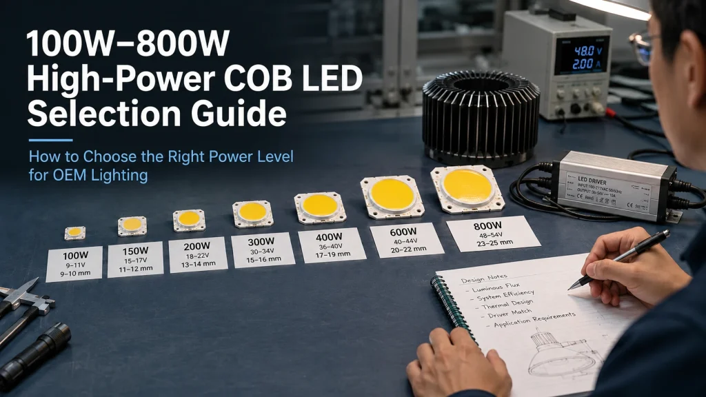
For high power COB LED, wattage selection should begin with the required lighting result, not a preferred number on a product label. A 200W COB LED is not automatically twice as bright as a 100W model, and an 800W module may be unsuitable if the driver, optics, heat sink, or enclosure cannot support it. For OEM lighting projects, the correct power level is the lowest practical configuration that meets the required output, beam, working distance, color quality, and operating conditions.
Define the Required Light Result Before Choosing COB Wattage
Convert the Application Into Measurable Optical Targets
“More brightness” is not a complete purchasing specification. First determine which measurement describes the application:
- Lumens indicate total light output.
- Lux indicates illumination on a target surface.
- Candela describes directional intensity.
- Beam angle shows how the output is distributed.
- Working distance defines how far the light must travel.
- Illuminated area establishes the required coverage.
A floodlight may require broad, uniform lux across a large surface, while a projection or long distance system may depend more heavily on center beam intensity and optical concentration. Two COBs with similar lumen output can produce different results when their light emitting surface, reflector, lens, or beam angle differs.
Before selecting a 100W, 200W, 500W, or 800W COB LED module, document the target distance, beam pattern, illuminated area, minimum acceptable output, and test conditions. If these values are unknown, it is recommended to measure the existing system before increasing power.
Identify Optical Losses Before Increasing Power
Weak output does not always mean that the COB wattage is too low. Light may be lost through an unsuitable reflector, poorly matched lens, thick diffuser, protective glass, incorrect focal position, contaminated optical surface, or excessive operating temperature.
Check whether the existing COB is being driven at its intended current and whether the optical system captures the complete emitting area. A larger or differently positioned LES may reduce center intensity even when total power increases. High CRI, specialized spectra, and warmer color temperatures may also affect usable output, depending on the product and test conditions.
Improving the reflector, lens alignment, thermal path, or driver operating point may provide a better result than replacing a 100W COB with a 200W unit.
Compare 100W–800W COB LEDs as System Classes
Power levels should be treated as system classes rather than fixed application categories. The appropriate class depends on the complete electrical, optical, thermal, and mechanical design.
| Decision factor | Around 100W | Around 200W | Around 500W | Around 800W |
| Driver requirements | Confirm current and full Vf range | Higher output capacity may be required | Specialized or multichannel architecture may be needed | Driver architecture becomes a major design constraint |
| Thermal design | Complete thermal path still required | Larger heat sink or airflow may be necessary | Active cooling becomes more likely | Thermal design may control the entire enclosure |
| Optical considerations | LES and reflector compatibility | Greater source density may affect beam design | Optical efficiency becomes critical | High optical and thermal density require close validation |
| Mechanical impact | PCB and mounting compatibility | Increased heat sink volume and weight | Space, wiring, and structural support become significant | A complete fixture redesign may be required |
| Purchasing approach | Standard or modified module | Standard or custom solution | Project-specific evaluation | Often requires system-level engineering review |
These categories are screening tools, not performance promises. Professional COB portfolios commonly differentiate products by LES, lumen output, efficacy, CRI, test current, thermal resistance, and supporting optical and mechanical systems—not wattage alone.
OEM teams can examine the available high-power COB LED module range after defining the application inputs, but each listed product still needs to be checked against the approved specification and final equipment design. IHY currently presents high power products ranging from a published 120W model to higher power configurations on its category page.
Choose One High-Power COB or Multiple Lower-Power COBs
A single high power COB may suit a compact optical system that requires one focal point, a concentrated beam, or simplified alignment. However, concentrating the complete load in one source can increase thermal density and make the driver, cooling system, and optical design more demanding.
Multiple lower power COBs may improve heat spreading, surface uniformity, redundancy, and mechanical flexibility. They can also increase the number of drivers or channels, wiring complexity, optical alignment work, assembly time, and possible differences between sources.
Compare the complete system rather than the COB unit price. Important factors include:
- Required beam shape and uniformity
- Available heatsink area
- Driver and channel architecture
- Fixture dimensions
- Failure tolerance
- Service and replacement method
- Assembly and qualification cost
One 800W COB does not inherently hold an advantage over 200W COBs. The result depends on whether the application prioritizes a concentrated source, distributed output, thermal spreading, or field serviceability.
Match the Power Level to the Electrical Architecture
Confirm Current, Forward Voltage, and Driver Availability
COBs with similar wattage can require substantially different voltage and current combinations. A higher voltage, lower current architecture may reduce conductor current and voltage drop, but it requires a driver with a suitable constant current output window. A lower voltage, higher current module may fit certain DC systems but can require larger conductors, stronger terminals, wider PCB traces, and closer control of contact resistance.
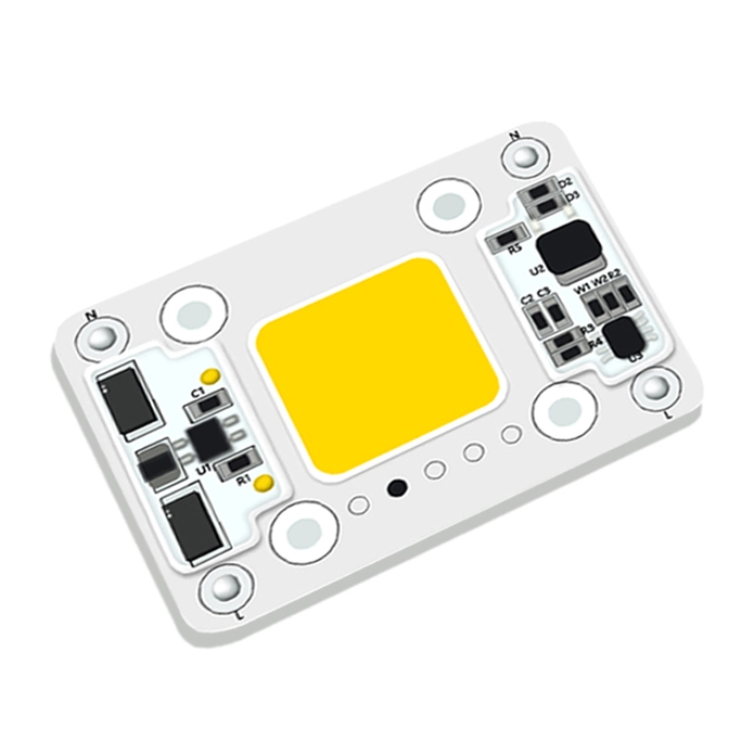
IHY’s published N1313 78V 120W high-power COB LED is listed at 78V, 1.5A, 120W, 3500K, and 54 × 46 × 2 mm on an aluminum base plate. It provides a useful example of a relatively high voltage, lower current configuration. Final driver selection should still use the approved minimum, typical, and maximum Vf values rather than the nominal 78V figure alone.
When evaluating any high power COB, request:
- Recommended and maximum operating current
- Minimum, typical, and maximum forward voltage
- Voltage test temperature
- Number of channels
- Series and parallel configuration
- Dimming requirements
- Electrical and power reduction under high temperature
Driver availability can influence the COB architecture. If a standard driver cannot cover the current and voltage combination, modifying the COB configuration may be more practical than adding multiple conversion stages.
Separate Rated Power From Continuous Usable Power
Rated power does not establish how much power the COB can use continuously inside the finished fixture. The sustainable operating point depends on ambient temperature, heat sink capacity, airflow, thermal interface quality, mounting, enclosure design, and the module’s temperature limits.
A COB that operates at its rated power on an open test bench may require under driving inside a compact or sealed enclosure. On the other hand, selecting a lower power class doesn’t automatically solve the thermal problem if the mounting surface, thermal interface, or ventilation is poor.
Validate the selected power under representative conditions. Record electrical input, COB case temperature, driver temperature, optical output, and temperature stabilization inside the intended enclosure. Use the supplier’s specified measurement point and limits.
Check Thermal and Mechanical Feasibility
Decide Whether Passive Cooling, Forced Air, or Derating Is Required
As power increases, the required thermal path generally becomes more demanding. Passive cooling may suit equipment with adequate heat sink area, open airflow, and moderate ambient temperature. Forced air cooling may be considered when space is limited or heat density is high, but fans add noise, dust exposure, maintenance requirements, power consumption, and another possible failure point.
Sealed outdoor products, dusty industrial equipment, quiet studio systems, and high temperature environments create different constraints. A 500W or 800W COB may be electrically available but mechanically impractical if the required cooling system cannot cannot fit within the fixture enclosure.
Do not approve a power level after a short illumination test. Thermal testing should continue until temperatures stabilize under the intended orientation, enclosure, input power, ambient condition, and duty cycle.
Confirm PCB, Mounting, and Enclosure Constraints
Higher power can require a larger PCB, increased contact area, heavier heat sink, different connector, or additional mounting support. Confirm:
- Board dimensions and thickness
- Mountinghole pattern
- LES location and optical center
- Electricalpad and connector position
- Heatsink contact area
- Available enclosure volume
- Wiring clearance
- Structural support and mounting pressure
Substrate/PCB material should not be judged by name alone. Aluminum, copper, ceramic, and other constructions can have different advantages, but overall performance also depends on dielectric layers, board structure, contact area, thermal interface, and assembly quality.
Match LES and Optical Density to the Required Beam
Select LES Size and Power Density Together
LES size influences how the source interacts with a reflector, lens, projection path, or light guide. A smaller LES may support tighter beam control in some systems, while a larger LES may provide broader emission or distribute heat across a wider area.
Increasing wattage without checking LES can reduce optical efficiency. A reflector designed for a smaller emitting surface may fail to collect or focus a larger source correctly. Concentrating very high power into a compact LES can also increase thermal and optical density.
Request LES dimensions, mechanical drawings, optical reference points, luminous flux test conditions, CCT, CRI, and relevant spectral information. Custom LES development may be justified when standard products cannot meet the required beam and mounting conditions simultaneously.
Upgrade or Replace a COB Without Creating a New Failure
Replacing a 100W COB with a 200W model is not a plug and play power upgrade.
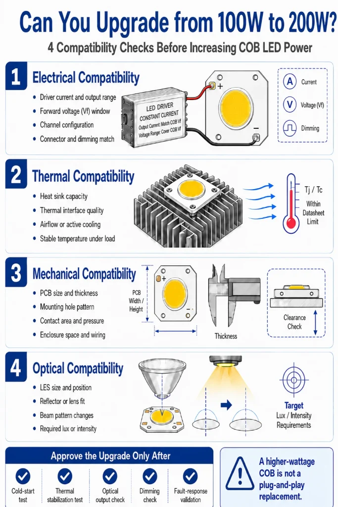
Confirm four forms of compatibility:
- Electrical: current, Vf range, channels, driver, connector, and dimming
- Thermal: heat load, thermal resistance, contact area, and cooling system
- Mechanical: PCB dimensions, mounting holes, thickness, and LES position
- Optical: output, LES, CCT, CRI, reflector, lens, and beam pattern
The existing driver may fail to meet the updated current or voltage requirements. The heat sink may be insufficient. Even if the new board fits, a changed LES can shift the focus or alter the beam.
After replacement, repeat cold-start, thermal, optical, dimming, and fault-response testing. An upgrade that increases input power but reduces optical compatibility may deliver less useful light while creating greater thermal stress.
Choose Between a Standard and Custom High Power COB
A standard module is appropriate when its voltage, current, LES, PCB dimensions, color specification, and thermal interface fit the product without major redesign. Customization becomes relevant when the equipment requires a nonstandard voltage current combination, unusual board shape, specific LES, multichannel structure, restricted mounting space, specialized spectrum, or closer integration with the driver and optics.
Shenzhen IHY Lighting Co., Ltd. describes its business as the development and production of mid to high end COB LEDs, LED modules, integrated driver modules, optical modules, and application-specific solutions. A custom COB LED light engine manufacturer may be suitable when the project requires coordinated changes to the source, electrical architecture, board, and optics rather than a simple wattage substitution.
Customization should begin only after the application targets and acceptance criteria are defined. It cannot compensate for an unclear optical requirement, insufficient cooling space, or unverified driver design.
Prepare a Power Level RFQ and Evaluate the Supplier
A useful RFQ should describe the application rather than requesting “a 500W COB.” Include:
- Target lumens, lux, or candela
- Working distance and illuminated area
- Beam-angle requirement
- Available input power and driver limits
- Maximum PCB and heatsink dimensions
- Cooling method and ambient temperature
- LES and optical constraints
- CCT, CRI, or spectrum
- Duty cycle
- Existing module or replacement data
- Sample quantity and estimated production volume
A qualified supplier should return comparable technical evidence, including recommended operating power, current, complete Vf range, channel configuration, luminous output with test conditions, LES, temperature limits, mechanical drawings, driver requirements, and sample approval conditions.
Shenzhen IHY Lighting Co., Ltd. publishes high power COB products and application focused development capabilities, but final decisions should be based on project specific drawings and approved specifications.
Conclusion
The right high power COB LED is not the highest wattage available. It is the lowest practical power architecture that satisfies the optical target while remaining compatible with the driver, LES, thermal path, enclosure, mounting, and operating environment.
For a project review, prepare the application, target output, distance, beam, available driver, cooling method, dimensional drawing, current COB model, sample quantity, and expected volume. These details can be provided through submit a high-power COB LED project inquiry so that Shenzhen IHY Lighting Co., Ltd. can assess whether a standard power class or custom configuration should be evaluated.
Frequently Asked Questions About COB LED Wattage
Is a 200W COB LED twice as bright as a 100W COB LED?
Not necessarily. Usable brightness also depends on efficacy, drive current, operating temperature, LES, CRI, optical losses, and beam distribution.
Can a 100W COB LED be replaced with a 200W model?
Only after checking the driver, Vf range, current, cooling, board dimensions, mounting, LES, and optics. Matching shape or voltage alone is insufficient.
When does a project need a 500W or 800W COB LED?
These levels should be evaluated when the required optical result cannot be achieved efficiently with a lower power or multisource design and the equipment can support the electrical and thermal load.
Is one 800W COB better than four 200W COB LEDs?
It depends on beam control, uniformity, heat spreading, driver architecture, redundancy, enclosure space, assembly complexity, and service requirements.
What information is needed before selecting COB LED wattage?
Define the optical target, working distance, beam angle, available driver, cooling method, LES constraints, dimensions, ambient temperature, duty cycle, and required color or spectrum.