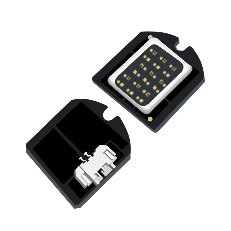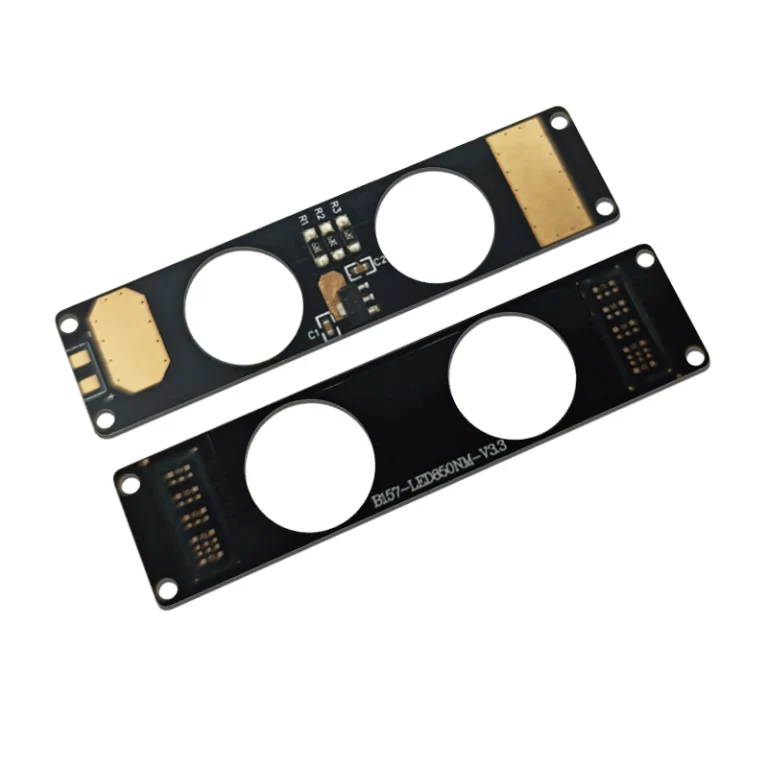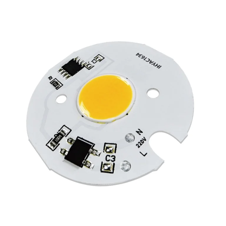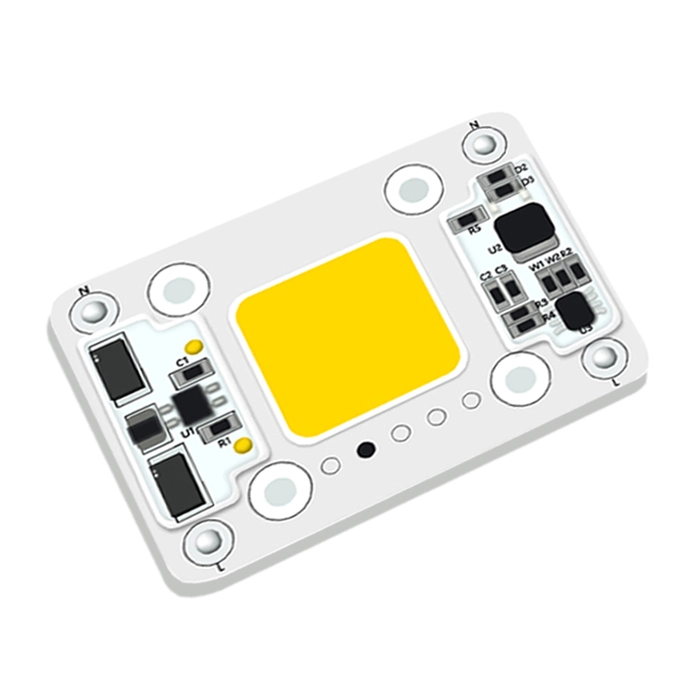




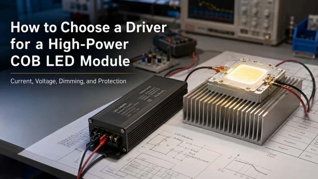
Choosing a high power COB LED driver by wattage alone can cause no start conditions, flicker, thermal shutdown, weak output, or LED damage. The driver must match the COB’s operating current and full forward voltage range while fitting the available input supply, dimming system, protection requirements, and operating temperature. For an OEM or repair team, the practical task is to identify the module’s electrical boundary, compare the correct driver specifications, and validate both components inside the finished equipment.
Identify the COB Module Type Before Selecting a Driver
The first question is not “What wattage driver is needed?” It is “What type of LED assembly is being powered?”
Distinguish a Bare COB From a Regulated DC or Integrated AC Module
A bare high power COB normally requires a regulated constant current source.A regulated DC module may contain onboard current control, while an integrated AC module may include driver components. Applying the wrong supply type can cause blinking, low output, or startup failure.
Do not assume that a module labeled “36V” can connect to any 36V constant voltage supply. Confirm whether the figure is forward voltage, regulated module input, or a nominal value for onboard electronics. Ask for the wiring diagram, polarity, channel configuration, and a clear statement of whether an external driver is required.
Collect the Electrical Data Before Searching for a Driver
Obtain the recommended operating current, maximum current, minimum/typical/maximum Vf at the intended current, test temperature, polarity, and channel structure. For multichannel COBs, obtain separate data for each channel.
Temperature and production variation can change the voltage needed to maintain current. If only a nominal voltage is available, request the full range. When the existing architecture is unsuitable, compare alternatives within the high power COB LED module range rather than forcing an incompatible driver into the design.
Match Driver Current, Voltage Range, and Output Power
A compatible driver must regulate the intended current while keeping the full COB Vf range inside its constant current output window. LED array guidance recommends constant current operation and requires the driver Vout range to cover the Vf range at the chosen drive level.
Select the Operating Current Before Comparing Wattage
Start with the current needed to reach the optical target without exceeding the COB’s electrical or thermal limits. Rated current may suit a fixture with adequate cooling. Under driving may be preferable in a compact enclosure, high ambient temperature, or application that does not require maximum output.
A higher wattage driver does not automatically force extra power into the COB. The immediate risk is an output current setting above the module’s limit. Compare regulated current, tolerance, voltage range, and thermal derating, not only label wattage. Required margin depends on maximum Vf, ambient temperature, enclosure, duty cycle, and the driver datasheet.
Keep the Full COB Vf Range Inside the Constant Current Window
The driver must supply enough voltage to maintain the target current at the highest expected Vf and remain regulated when Vf falls. A nominal “78V COB” therefore cannot be matched using 78V alone.
Use this sequence:
- Set the target operating current.
- Obtain the COB’s full Vf range at that current.
- Add Vf ranges for COBs connected in series.
- Compare the result with the driver’s constantcurrent window.
- Recheck the match during cold start and thermal steady state.
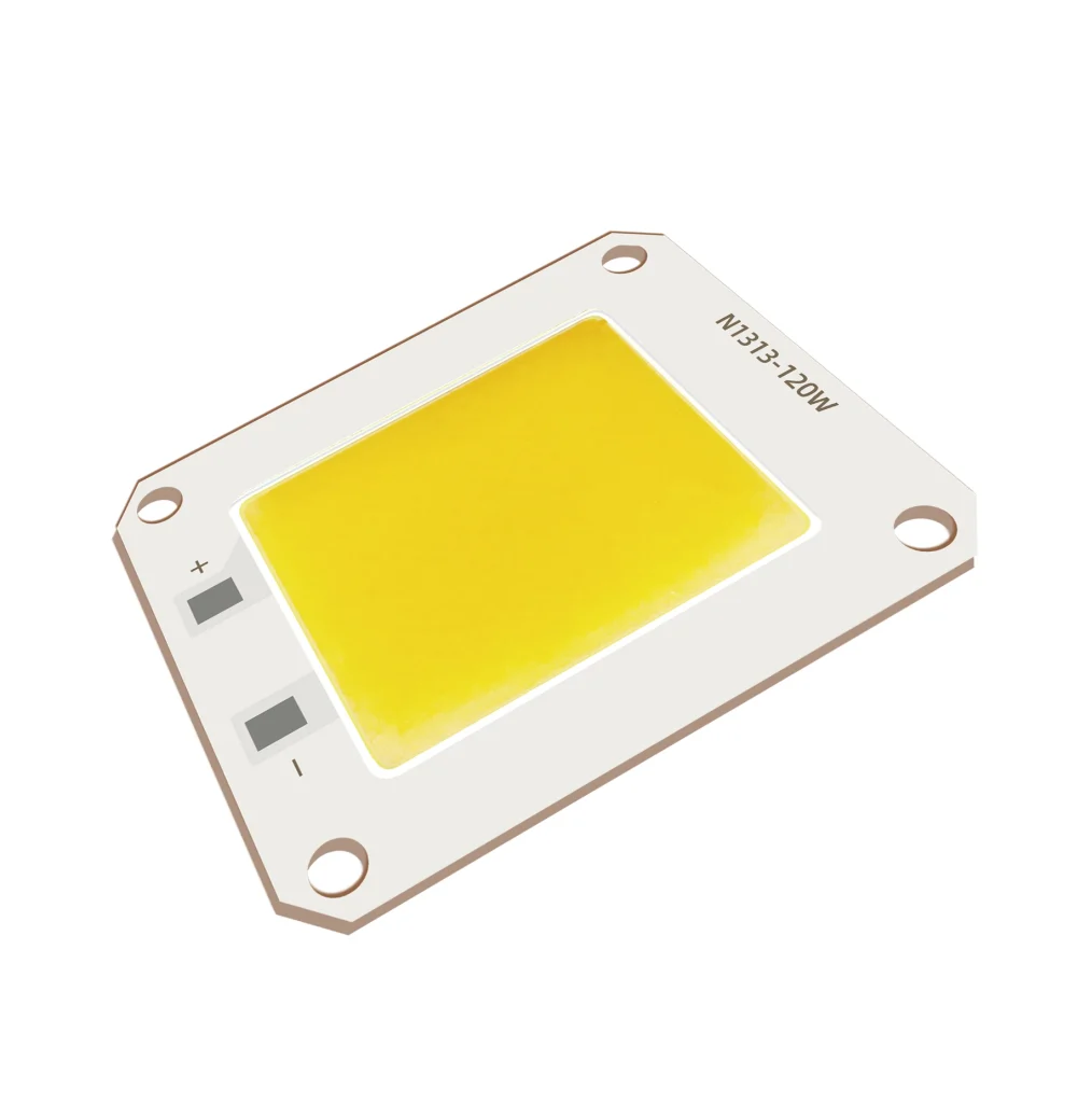
The published N1313 78V 120W high power COB LED data lists 78V, 1.5A, 120W, 3500K, and a 54 × 46 × 2 mm aluminum substrate. It illustrates a higher voltage, lower current architecture, but final driver approval still requires the complete Vf range and approved current limits.
Choose the Input Architecture and Driver Topology
After defining the output requirements, match the driver to the available source.
Match AC-DC or DC-DC Operation to the Power Source
A mains powered fixture may use an AC-DC constant current driver. A system supplied from an industrial DC bus, vehicle, or battery may use a DC-DC stage. If input voltage stays above the required LED voltage, a buck topology may fit; if it stays below, a boost stage may be needed. When input crosses the COB Vf, buck boost operation may be considered.
Also consider isolation, serviceability, electrical noise, wiring, and enclosure space. Cascading a constant voltage supply with an onboard DC-DC stage can create start up problems when rise time, current limit, and converter behavior are not evaluated together.
Compare High Voltage and High Current COB Systems
A higher voltage, lower current COB can reduce conductor current and voltage drop but needs a driver with a sufficiently high output window and suitable insulation design. A lower voltage, higher current system may fit low voltage buses, yet it can require larger conductors, stronger terminals, wider PCB traces, and tighter control of contact resistance.
Review driver availability, safety boundaries, wiring length, connector limits, and controls together. If no standard driver fits, changing the COB architecture or using an integrated light engine may be more practical than adding conversion stages.
Specify Dimming, Flicker, and Control Performance
A driver that works at full output may still fail at low brightness. “Dimmable” is not a complete specification.
Match the Dimming Interface to the Final System
Confirm whether the controller provides PWM, analog current control, 0–10V, DALI, or another signal. Check signal voltage, frequency, polarity, isolation, minimum dimming level, dim to off behavior, and multichannel requirements. A mismatch can cause flicker, dead zones, failure to turn off, or inconsistent behavior after replacement.
PWM frequency requires extra attention in studio, stage, inspection, and machine vision systems because unsuitable frequency can create stroboscopic effects and fast switching can introduce electrical noise. Test with the actual controller, wiring, load, enclosure, and temperature; formal flicker limits require suitable measurements.
Prevent Failures and Replace an Existing COB LED Driver
A replacement selected only by input voltage and wattage can repeat the original failure.
| Compatibility area | What to verify |
| Input | AC voltage/frequency or DC range, inrush, site conditions |
| Output | Regulated current, tolerance, voltage window, power range |
| Control | Dimming interface, signal range, minimum level |
| Protection | Open load, short circuit, over voltage, over temperature behavior |
| Physical | Dimensions, connector, enclosure, mounting, temperature rating |
No start can result from an inadequate voltage window, wrong polarity, protection cycling, or DC-DC startup mismatch. Flicker may come from dimming incompatibility, unstable input, poor connections, or loss of regulation. Warm shutdown may indicate thermal protection, excessive COB temperature, or inadequate ventilation. Check the COB, wiring, cooling, controller, and input supply before replacement.
Validate the COB and Driver as One System
A short bench test is not production approval. Install the COB, driver, controller, heat sink, wiring, and enclosure in a representative sample. Test cold start, minimum and maximum input, full output, minimum dimming, repeated startup, fault response, and thermal steady state.
Record current, LED voltage, driver temperature, COB case temperature, flicker, and protection response. Confirm that regulation is maintained as the system warms. Guidance also recommends testing electrical behavior and temperature with the complete luminaire.
When multiple COBs use one driver, series connection can maintain the same current through each unit if total Vf remains within the driver window. Direct parallel connection can produce unequal current sharing when Vf differs, so separately regulated channels may be required.
Prepare an RFQ and Evaluate the Integration Supplier
An RFQ should include the COB model, target current, full Vf range, input source, dimming method, ambient temperature, enclosure, cooling, sample quantity, expected volume, and failure symptoms or photographs.
For the COB, confirm current limits, Vf range, test conditions, channel configuration, polarity, and thermal limits. For the driver, confirm regulated current, voltage window, input range, thermal derating, dimming, protection, dimensions, and environmental rating. Resolve missing units or inconsistent voltage current power values before ordering samples.
Shenzhen IHY Lighting Co., Ltd. presents its business around customized COB products and the integration of COB sources, IC drivers, passive components, power management, and optics. A custom COB LED light engine manufacturer is relevant when the project needs coordinated source and driver development instead of an isolated component purchase.
Conclusion
Choosing a high power COB LED driver starts with the module type, not wattage. Set the operating current, match the full Vf range to the constant current window, confirm input architecture, specify dimming and protection, and validate the complete assembly under cold and hot conditions.
For a compatibility review, prepare the COB model or datasheet, electrical limits, input supply, controller, drawing, enclosure and cooling conditions, sample quantity, expected volume, and failure photographs. These details can be provided through submit a COB LED and driver compatibility inquiry so Shenzhen IHY Lighting Co., Ltd. can assess whether a standard COB, modified electrical configuration, or integrated light engine should be evaluated.
Frequently Asked Questions
Do high power COB LEDs need constant current drivers?
Bare high power COB LEDs generally use constant current drive. A regulated DC or integrated AC module may have onboard current control, so check its specified input boundary first.
Can a higher wattage LED driver damage a COB LED?
Higher driver wattage alone does not cause damage. Excessive regulated current, an unsuitable output voltage range, incorrect wiring, or incompatible protection behavior creates the greater risk.
What voltage driver is needed for a 78V COB LED?
Choose a constant current driver whose output window covers the COB’s complete Vf range at the selected current and operating temperatures. The nominal 78V value alone is insufficient.
Can two COB LEDs share one constant current driver?
They may be connected in series if the same current is required and combined Vf stays within the driver window. Parallel operation needs current balancing or independent channels.
Why does a COB LED flicker or shut down after warming up?
Possible causes include an inadequate voltage window, driver over temperature protection, COB overheating, dimming incompatibility, unstable input power, or poor connections. Test again after thermal steady state.