



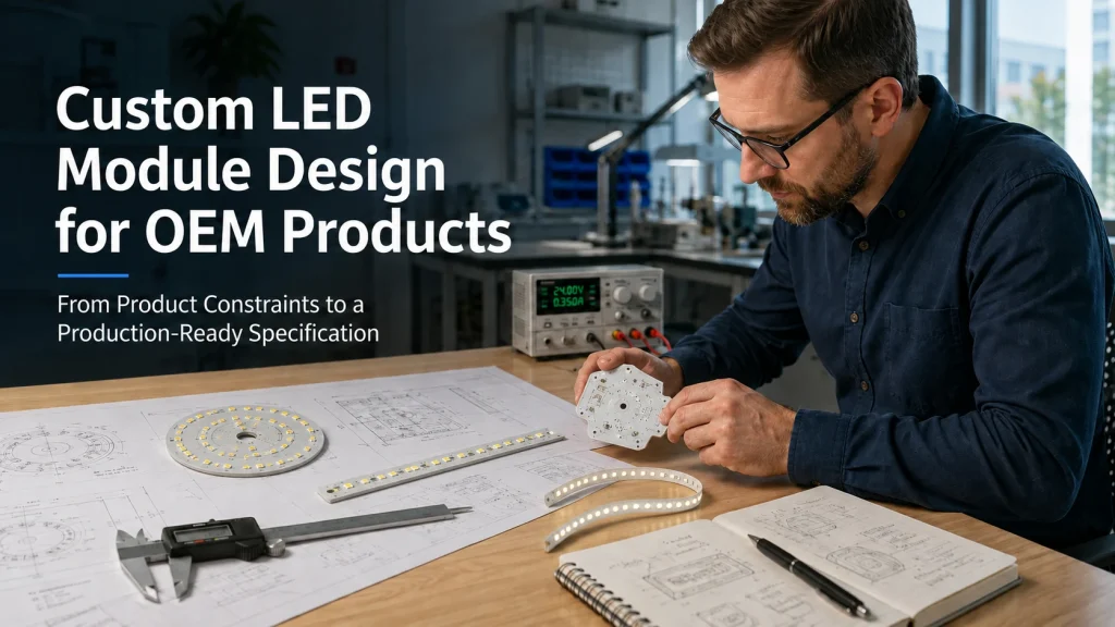
Custom LED module design becomes necessary when an OEM product cannot use an existing light source without compromising its housing, optics, power system, thermal path, or assembly process. The task is not simply to request a different PCB shape. It is to convert product constraints into measurable requirements that a supplier can quote, design, prototype, test, and reproduce.
When Does an OEM Product Actually Need a Custom LED Module?
Use a Standard Module Unless a Critical Interface Cannot Be Matched
A standard module is usually the lower risk choice when its outline, mounting method, electrical input, light-emitting surface, connector, and thermal interface fit the product. Engineers should first review available LED modules for OEM equipment and determine whether the remaining gap can be solved by changing the driver, lens, heatsink, wiring, or enclosure.
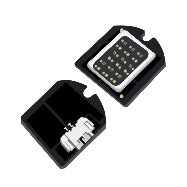
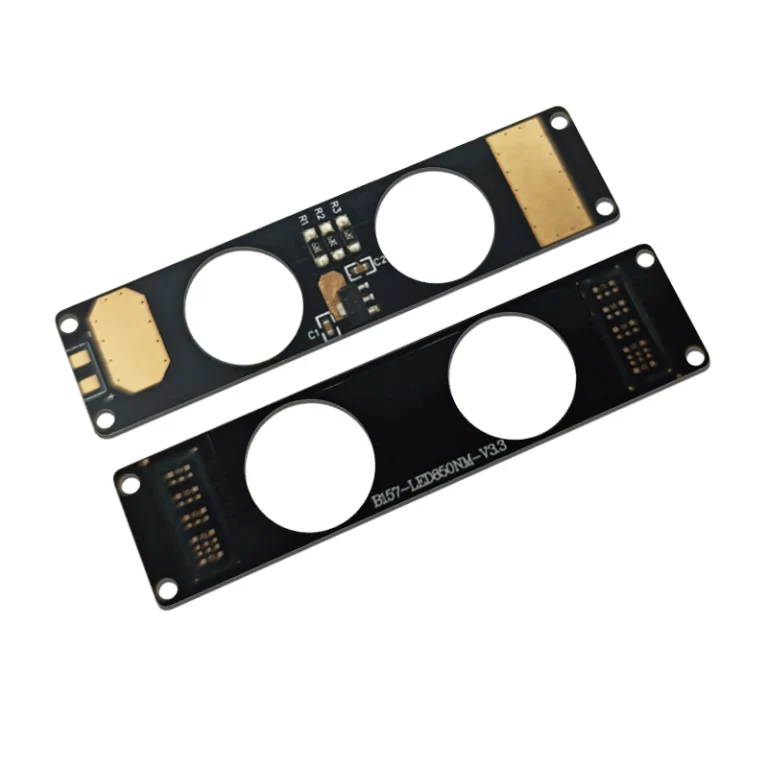
Customization becomes reasonable when a mandatory interface cannot be matched. Typical triggers include a restricted cavity, unusual PCB outline, fixed lens position, special voltage or channel arrangement, flexible construction, UV or IR output, or integrated connectors and controls.
Separate Fixed Constraints from Preferred Features
Fixed constraints make the product impossible to assemble or operate if they are missed, such as maximum dimensions, mounting points, available power, optical position, or environmental limits. Preferred features may include a target brightness, proposed connector, or desired board shape that can still be adjusted.
Classify requirements as mandatory, target, acceptable range, or supplier-proposed. This creates room to resolve conflicts before cost, size, output, and temperature targets compete.
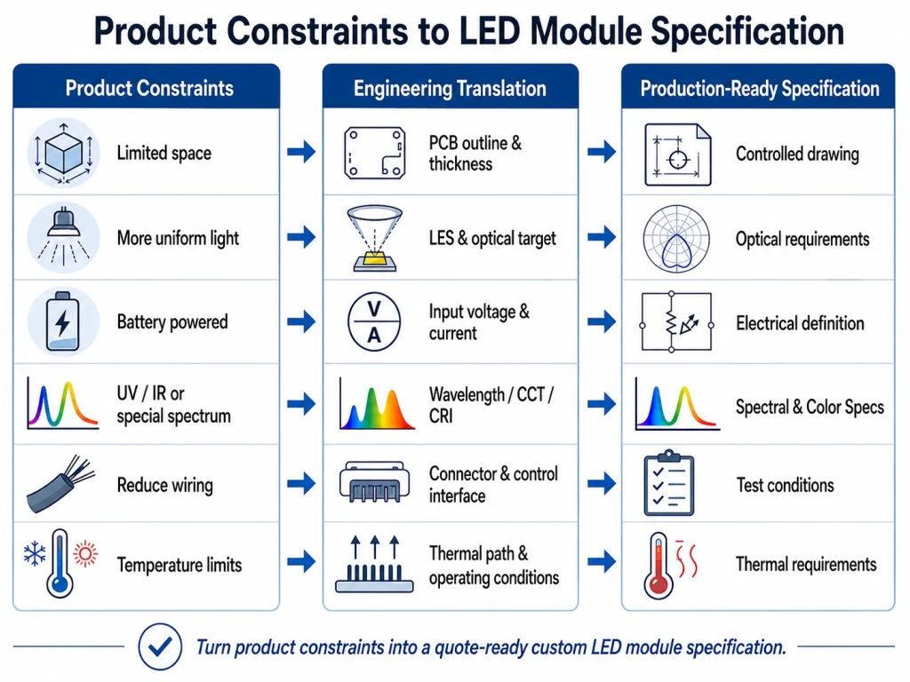
Translate Product Constraints into Measurable Engineering Requirements
Define the Mechanical Envelope and Assembly Interface
A custom-shape LED module should begin with the complete mechanical envelope, not a rough outer dimension. The drawing should identify maximum length, width, and thickness; mounting holes; datum points; keep-out areas; connector clearance; wire-exit direction; LES position; thermal-contact area; and critical tolerances.
Flexible modules can suit curved housings, rings, or narrow cavities. They may be unsuitable where the bend location is uncontrolled, the board lacks support, or the heat path cannot handle the intended load.
Convert the Optical Goal into Output, LES, Beam, and Spectrum Data
Terms such as “brighter,” “more focused,” or “more uniform” are not sufficient engineering requirements. Brightness should be translated into the metric that reflects the application: lumens for total output, lux at a specified distance for illumination, candela for beam intensity, or radiant output for UV and IR systems.
The light-emitting surface affects lens matching, beam shape, center intensity, and uniformity. A larger LES may suit a broad source but may not work with a compact focusing optic. Color requirements should specify CCT, CRI, R9, color tolerance, RGB/RGBW channels, or wavelength data as applicable. COB specific projects can use the custom COB LED design guide for deeper discussion of LES, substrates, and validation.
Define the Electrical, Driver, and Control Architecture
The electrical specification should state the available power source and distinguish accepted input voltage from LED forward voltage. Battery-powered equipment, a regulated 12 V or 24 V bus, an external constant-current driver, and direct-AC designs create different requirements. Rated current, power limit, polarity, dimming method, and channel arrangement should be recorded.
Driver-module matching requires comparison of voltage, current, and power ranges rather than wattage alone; Zhaga treats these parameters as central to assessing whether a combination is viable. If drivers or controls may be integrated onto the PCB, the specification should define which functions belong to the module and which remain in the OEM product.
Define the Thermal Path and Supply Boundary
A substrate name does not describe the complete thermal design. The project should identify power, power density, duty cycle, ambient temperature, enclosure type, contact area, interface material, mounting method, and any housing or heatsink used to remove heat.
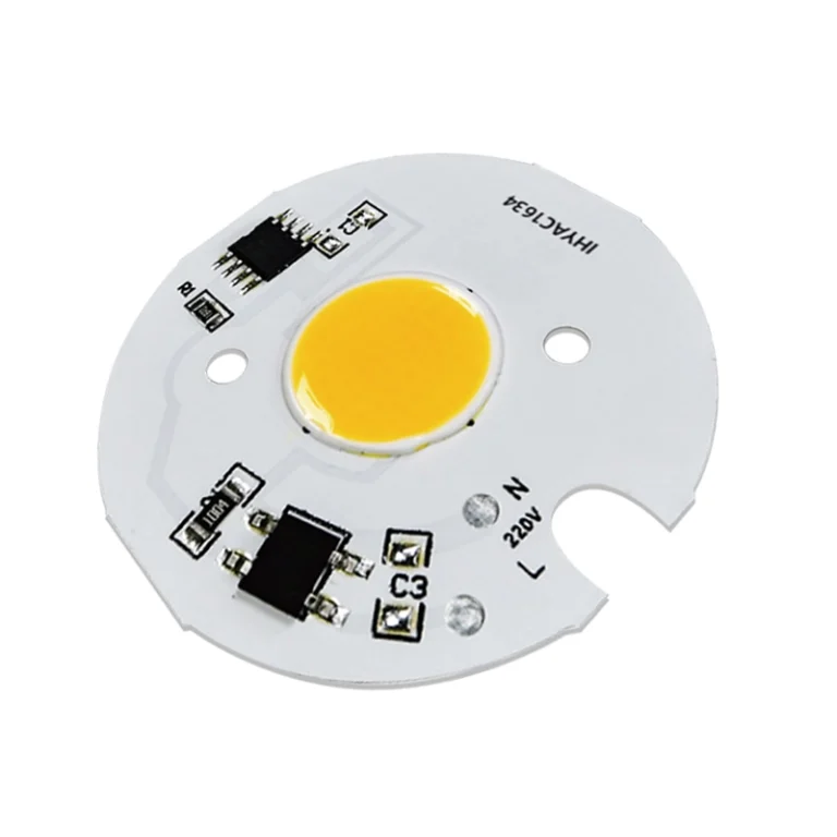
The supply boundary should be equally clear. Under IES terminology, an LED module may include LEDs on a PCB or substrate with additional interfaces, while a light engine includes a driver and other system components. Review LED module vs LED light engine before assigning responsibility for the driver, optics, connectors, protection, and controls.
Resolve Requirement Conflicts Before PCB Layout
Balance Size, Output, Voltage, and Heat
Reducing board area while maintaining output raises power density. Reducing the LES may help a focusing optic but concentrate heat. Lower voltage can require higher current, increasing voltage drop and connector demands.
| Requested Change | Likely Trade Off | Requirement to Recheck |
| Smaller PCB | Higher power density | Output, substrate, contact area |
| Smaller LES | Concentrated heat | Current, optics, housing |
| Lower voltage | Higher current | Wiring, connector, voltage drop |
| Higher output | More electrical and thermal load | Driver, duty cycle, cooling |
| Flexible construction | Reduced heat spreading or support | Power density, mounting, bend control |
The correct design meets mandatory constraints under documented operating conditions.
Balance Integration with Assembly and Serviceability
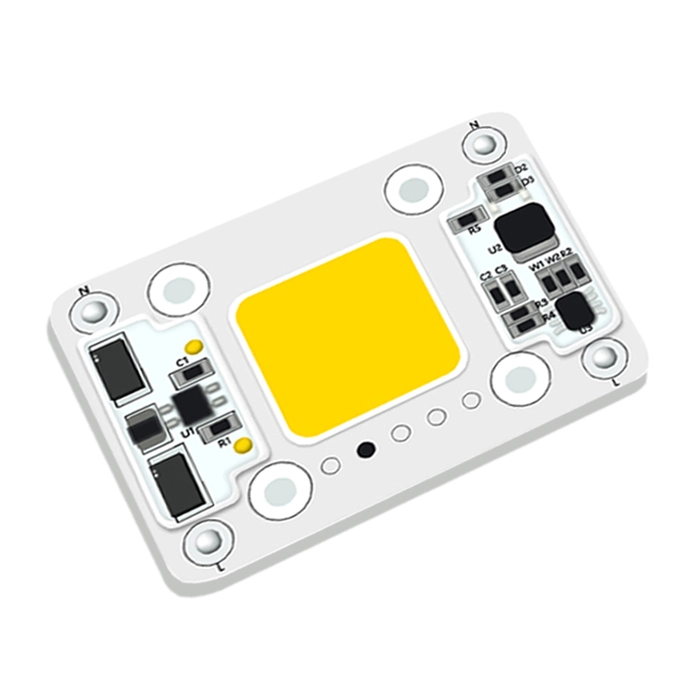
Integrating a driver, regulator, connector, sensor, or controller can reduce wiring and assembly steps. It can also increase board area, heat concentration, component dependency, and replacement complexity.
The specification should define responsibility for every supplied part. Shenzhen IHY Lighting Co., Ltd. publicly presents custom geometry, optical and spectral configurations, voltage and current adaptation, substrate options, and component integration within its custom module scope. Its confirmed customization framework also covers geometric, optical, electrical, substrate, and circuit integration dimensions.
Build a Quote-Ready Custom LED Module Specification
Prepare Controlled Drawings and Interface Definitions
A quote-ready package should include the PCB outline, LES location, mounting references, keep out zones, connector and polarity information, thermal-contact surface, critical tolerances, and drawing revision. It should identify which dimensions are fixed and where the supplier may make design for manufacturing adjustments.
IPC’s board-design resources emphasize manufacture ability review, documentation, dimensioning, tolerancing, and requirements for rigid and flexible boards. The objective is to replace verbal assumptions with controlled information.
Define Test Conditions, Acceptance Criteria, and Commercial Inputs
Specify the intended driver, working distance, lens or diffuser, housing, thermal interface, ambient condition, stabilization method, and duty cycle. Acceptance criteria may cover output, beam, color or spectrum, voltage and current, temperature, dimensions, assembly fit, and control behavior.
The RFQ should also state the prototype purpose, sample quantity, estimated demand, project stage, available tooling or reference samples, and any confirmed cost boundary. These details distinguish an early feasibility study from a production-intent design.
Check Manufacture ability Before Approving the Prototype
Complete a DFM Review Before Fabrication
Review board outline feasibility, component clearance, routing, connector access, polarity, test points, thermal contact continuity, bend direction, support, coating boundaries, and critical tolerances before fabrication. Custom-shape, flexible, and highly integrated boards need particular attention because small mechanical changes can affect routing or heat spreading.
Each DFM adjustment should identify its reason, affected dimensions, and required verification.
Validate the Prototype Inside the Final Product
A prototype that lights on a bench is not production-ready. Test it with the intended driver, controls, optics, housing, heatsink, thermal interface, connector, wiring, duty cycle, and ambient conditions. Flicker, dark zones, unexpected beam shape, connector heating, mechanical interference, or color mismatch often indicate a system interface problem rather than a defective LED alone.
Record the sample revision, test setup, corrective action, and retest result. Freeze the design only when all approved documents and samples share the same revision.
How to Evaluate a Custom LED Module Supplier
A qualified supplier should show how the proposed design addresses the product constraints. Before sample approval, request a controlled drawing, electrical and connection data, optical results with test conditions, thermal assumptions, material identification, installation requirements, and a revision record.
Compare project scope and risk, not unit price alone. Confirm responsibility for driver selection, optical matching, PCB design, component sourcing, testing, sample revisions, and change communication. Shenzhen IHY Lighting Co., Ltd. offers COB LEDs, LED modules, and application specific solutions covering AC/DC/COB/SMD modules, flexible light sources, integrated assemblies, and UV/IR configurations. Projects requiring broader engineering review can be directed to custom LED module solutions.
Conclusion
A production-ready custom LED module specification begins by proving that a standard product cannot satisfy a critical interface. The OEM must then convert mechanical, optical, electrical, thermal, and assembly constraints into controlled drawings, measurable requirements, test conditions, and acceptance criteria.
For an initial review, contact IHY Lighting with the application, drawings or reference sample, available space, power and driver information, optical target, operating environment, prototype needs, and estimated quantity.
Frequently Asked Questions About Custom LED Module Design
When does an OEM need a custom LED module?
When no standard module can meet a mandatory mechanical, optical, electrical, thermal, spectral, or integration requirement.
Can an LED module be made in any shape?
Many shapes can be evaluated, but feasibility depends on routing, LED placement, thermal area, mounting, tolerances, and manufacturing processes.
What information is needed for a custom LED module quotation?
Provide the application, drawings or sample, dimensions, optical target, input and driver data, thermal environment, connector details, prototype quantity, and estimated demand.
Can the driver and control components be integrated onto the LED PCB?
They may be integrated when board area, thermal conditions, electrical architecture, and service requirements support it.
How should a custom LED module prototype be tested?
Test it inside a representative final product using production-intent power, controls, optics, housing, heat transfer parts, wiring, duty cycle, and environmental conditions.