



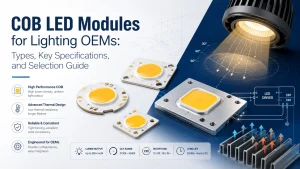
Selecting COB LED modules for lighting requires more than comparing wattage, lumens, or price. A module must match the driver, light-emitting surface, optics, thermal path, PCB dimensions, mounting method, and control system. Two modules with the same power may require different currents, produce different beams, or need different heatsinks.
This guide helps lighting OEMs, equipment manufacturers, engineers, and technical buyers identify module types, read specifications, assess replacements, prevent integration problems, and prepare an effective RFQ.
What Is a COB LED Module?
A COB LED module generally combines multiple LED dies on a shared substrate or PCB to create a compact emitting surface. The term does not confirm that a driver, connector, lens, protection circuit, or heatsink is included.
The Illuminating Engineering Society defines an LED array or module as LEDs or dies assembled on a PCB or substrate, possibly with optical, thermal, mechanical, and electrical interfaces, and intended for connection to the load side of a driver. A light engine also includes the driver and related system components.
COB LED Package vs COB Module vs LED Light Engine
A basic COB may be sufficient when the OEM already has a qualified driver, optical system, heatsink, and assembly method. A COB module may add a shaped PCB, connectors, or supporting electronics. A light engine provides a more integrated system.
Because suppliers may use these terms differently, buyers should request a dimensional drawing, connection diagram, input requirements, and clear supply boundary. The product name alone does not show whether the assembly can connect directly to the equipment power source.
What Types of COB LED Modules Are Available?
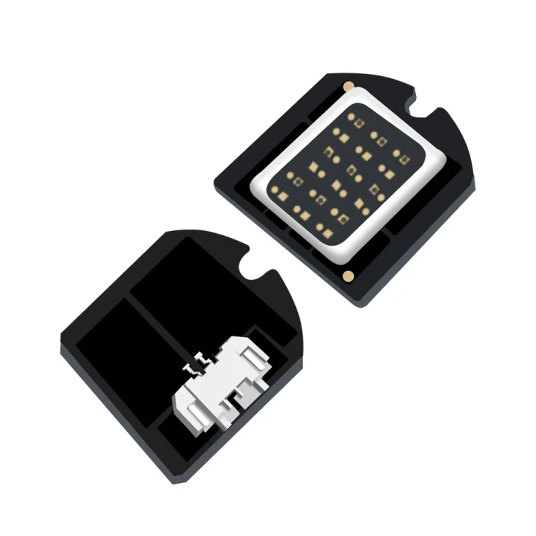
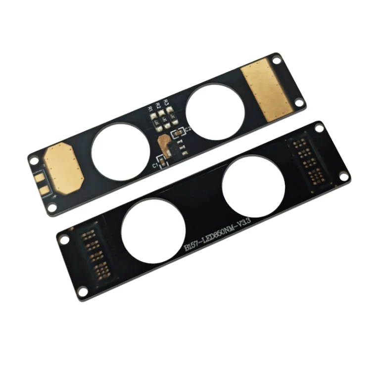
IHY’s published LED Module range includes DC, AC, UV/IR, and cinematic or studio-lighting categories, along with multicolor, connector equipped, and integrated electronics examples.
| Module type | Typical use | Buyer must verify |
| Basic COB or module | Existing external driver | Voltage, current, optics, heatsink |
| DC module | Low-voltage equipment | Constant-current or regulated-voltage input |
| AC or integrated module | Fewer external parts | Heat, dimming, protection |
| Multichannel module | Tunable-white or color control | Per-channel electrical data |
| Flexible or specialized module | Curved, IR, or UV products | Bending, heat path, wavelength |
OEMs still defining their architecture can review COB LED module options for OEM lighting before selecting a configuration.
Bare COB, DC, AC, and Integrated-Driver Modules
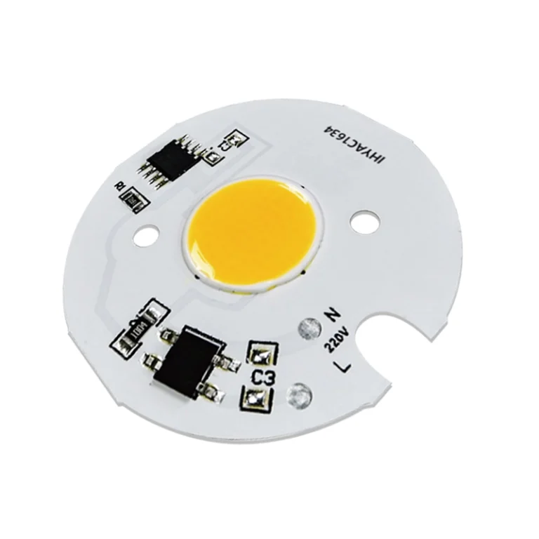
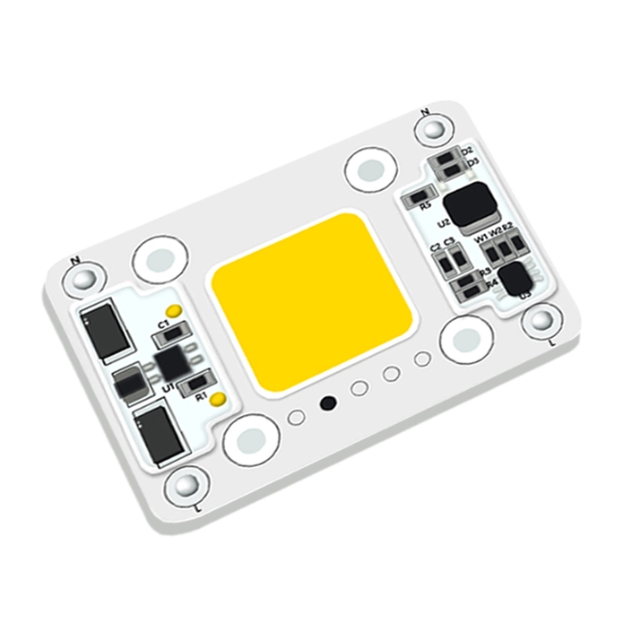
A basic COB normally needs an external driver. A DC module may accept a defined low voltage input or may still require constant-current regulation. An AC module includes electronics intended for a stated AC input, but it also raises questions about heat, dimming, protection, insulation, and serviceability.
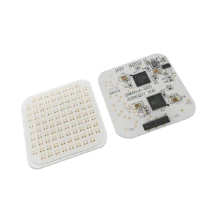
The IHY-XR02 DC COB LED module is listed at 2 V, 500 mA, and 1 W on a 24 × 24 × 0.8 mm aluminum PCB, with electronic components integrated on the board. Buyers should therefore confirm the input boundary and onboard functions instead of relying on the label “DC module.”
High-Power, Multichannel, Flexible, and Specialized Modules
High-power modules suit compact products that need substantial output but place greater demands on the driver, conductors, mounting interface, and heatsink. Multichannel products combine colors, CCTs, or wavelengths, yet each channel may need separate electrical data and control.
Flexible or shaped modules can fit curved housings and restricted spaces, but support, connector position, and heat spreading must be reviewed. IR and UV modules require wavelength-specific checks. Specialized features should be chosen only when they solve a defined application requirement.
How to Read COB LED Module Specifications
Lumens, Candela, LES, Beam Angle, CCT, and CRI
Lumens measure total emitted light, while candela describes intensity in a direction. For a spotlight, center beam intensity and working distance may matter more than total lumens. For close range fill lighting, emitting-area size and uniformity may be more important.
The light emitting surface, or LES, must match the lens or reflector. A smaller LES may support tighter beam control but can increase local power density. A larger LES may improve uniformity while requiring a larger optical system.
CCT, CRI, R9, color tolerance, or spectrum should match the application. Buyers should also confirm the current, temperature, and optical conditions under which published data were measured.
Voltage, Current, Power, Driver, and Dimming Compatibility
A driver should match the module’s forward voltage range, operating current, maximum power, channel configuration, and dimming method. Wattage alone is insufficient.
Low voltage, high current modules may require larger conductors and connectors and can be sensitive to cable voltage drop. Higher voltage designs need an appropriate driver. Multichannel modules require independent outputs or controls where specified.
Before approval, test the module with the intended production driver and controller. Check startup, full output, low level dimming, channel balance, and connector temperature.
Thermal Resistance, Tc, Substrate, Dimensions, and Heatsink Requirements
LED performance depends on the thermal path from the dies through the substrate, interface material, mounting surface, heatsink, enclosure, and ambient air. The IES notes that complete product reliability depends on more than the LED component, including drive circuitry and secondary optics.
A module that runs acceptably in open air may overheat inside a sealed housing. Confirm the case temperature measurement point, mounting requirements, thermal-contact area, duty cycle, and maximum ambient temperature.
Board outline, thickness, mounting holes, connector clearance, and surface flatness also affect assembly and heat transfer. Thermal testing should use the intended driver, housing, optics, interface material, and operating cycle.
How to Select a COB LED Module for the Application
Focused Lighting, Uniform Fill, and Compact Equipment
Focused products should prioritize LES, candela, focal position, optical diameter, and working distance. Uniform fill products should emphasize emitting area, diffuser distance, edge falloff, and visible hot spots. Compact equipment must balance output against PCB space, connector placement, and available heatsink area.
Select the module together with the optics and enclosure. Choosing the source first and forcing the mechanical design to accommodate it can create glare, poor focus, excess heat, or unnecessary product size.
Photography, Automotive, Medical, and Outdoor Requirements
Photography modules may require high color quality, stable dimming, and flicker evaluation. Automotive or mobile equipment may need review of input variation, space, vibration, and temperature. Medical-support, inspection, IR, and UV systems may require precise spectrum or wavelength data. Outdoor products must account for sealed enclosures and their effect on heat and optics.
A module specification cannot establish the compliance or service life of the complete product. Drivers, optics, seals, wiring, housing materials, and environmental exposure all affect final performance.
Can One COB LED Module Replace Another?
Use a Four Interface Compatibility Check
Modules with the same wattage are not automatically interchangeable. Compare:
- Electrical:voltage, current, driver, dimming, polarity, and connectors.
- Thermal:substrate, temperature limits, contact area, interface material, and heatsink.
- Mechanical:outline, thickness, holes, clearances, and connector orientation.
- Optical:LES, focal position, beam, CCT, CRI, and output.
A replacement may illuminate during a bench test yet still flicker, overheat, shift the beam, or fail to fit. Validate an engineering sample in the final equipment before approving the substitution.
Common COB LED Module Selection Mistakes
Overheating, Driver Mismatch, Flicker, and Poor Beam Quality
Overheating can result from excessive current, poor thermal contact, inadequate heatsink capacity, trapped enclosure heat, or high power density. Flicker may come from an incompatible driver, dimmer, input supply, or control signal. Poor beam quality can result from the wrong LES, focal distance, reflector opening, or diffuser spacing.
Troubleshoot in order: verify electrical input, inspect connections, record stabilized temperatures, review mechanical contact, and measure optical performance. Replacing the module without identifying the system cause may allow the same problem to recur.
How to Prepare a COB LED Module RFQ and Evaluate a Supplier
What Specifications Should Be Included in the RFQ?
A useful RFQ should include:
- Application and working distance
- Target lumens, candela, beam, or illuminated area
- LES and PCB size limits
- CCT, CRI, spectrum, or channel requirements
- Input, driver, current, power, and dimming
- Heatsink, housing, ambient temperature, and duty cycle
- Mounting, connector, and drawing requirements
- Prototype quantity and estimated annual demand
The supplier should return a defined supply boundary, drawing, electrical and optical specification, test conditions, sample plan, and installation requirements.
How to Evaluate Engineering, Documentation, and Change Control
A capable supplier should review how the module interacts with the driver, optics, thermal structure, housing, and controls. Buyers should request controlled drawings, documented measurement conditions, material identification, traceability, and a process for communicating changes.
Shenzhen IHY Lighting Co., Ltd. describes its business around structural design, optical engineering, electrical specifications, smart controls, and integration of COB sources, drivers, passive components, and power-management functions on a single PCB. Its custom COB LED light engine manufacturer positioning is relevant when a project needs coordinated integration rather than a catalog source alone.
Conclusion
COB LED module selection should begin by defining the supply boundary, optics, driver architecture, thermal path, and mechanical interfaces. Compare voltage, current, LES, color, dimensions, and test conditions—not wattage alone.
For a technical review, prepare the model, drawings, available space, input conditions, optical targets, thermal environment, sample quantity, estimated demand, and failure photographs. These details can be used to submit a COB LED module project inquiry to Shenzhen IHY Lighting Co., Ltd. for an initial compatibility or customization assessment.
Frequently Asked Questions About COB LED Modules
Does a COB LED Module Need a Driver?
A basic COB or module normally requires a compatible driver. Some AC or integrated modules include onboard electronics. Confirm the input and connection requirements.
How Do I Choose Between an AC and DC COB LED Module?
Choose according to the equipment power architecture, control method, thermal environment, maintenance strategy, and final product requirements.
How Do I Match a Heatsink to a COB LED Module?
Review power, thermal resistance, temperature limits, interface material, contact area, airflow, ambient temperature, and duty cycle. Validate temperature in the final housing.
Can a COB Module With the Same Wattage Replace an Existing One?
Not necessarily. Voltage, current, dimensions, mounting, thermal interface, LES, optics, color, driver, and controls must also be compatible.
Which Specifications Should Be Included in a COB Module RFQ?
Include the application, optical targets, LES, input and driver data, color requirements, PCB limits, mounting, thermal conditions, sample quantity, and expected demand.