



COB Lighting in Power Tools: A Practical Engineering Perspective
Case Study for OEM/ODM Tool Manufacturers
1. Introduction
For today’s power tools, lighting is no longer an afterthought, it’s a core part of the user experience, with direct implications for safety and brand identity. Whether on a compact cordless driver or a heavy duty industrial machine, integrated light engines offer clear task lighting, instant status indication, and a signature look.
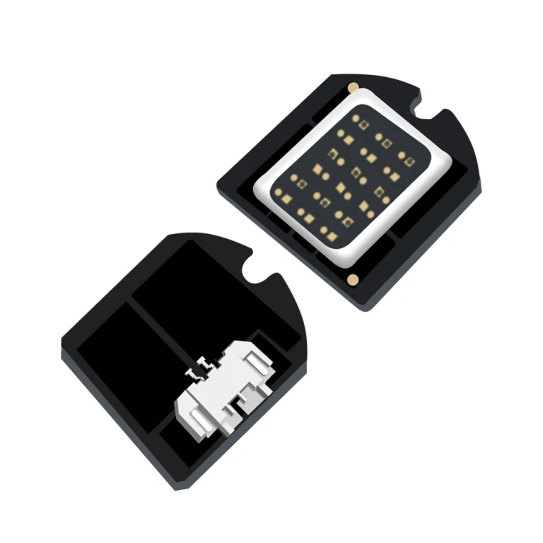
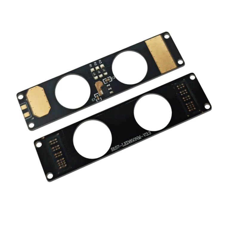
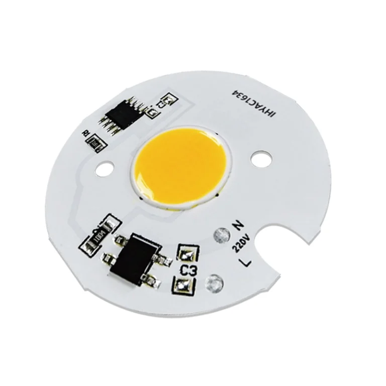
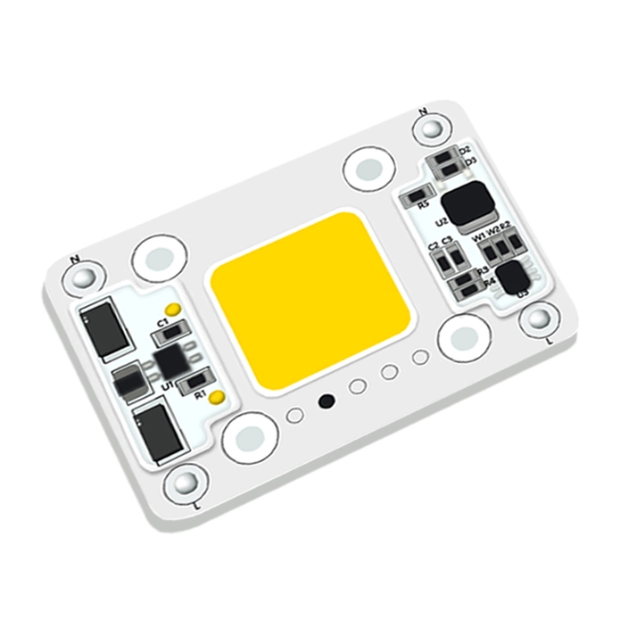
For OEM and ODM power tool manufacturers, selecting the better lighting technology is a crucial engineering decision. While traditional Surface Mount Device (SMD) LEDs continue to serve basic lighting needs, Chip on Board (COB) LED technology is rapidly reshaping product design. This article provides a practical engineering analysis of where COB lighting creates genuine technical value, where traditional LEDs remain appropriate, and how OEM manufacturers can integrate COB light engines into next generation tools.
2. Power Tool Categories & Illumination Requirements
Different power tool categories operate under distinct working conditions, requiring tailored optical, mechanical, and spatial lighting specifications.
| Tool Category | Representative Examples | Key Illumination Needs | Spatial & Mechanical Constraints |
| Portable Precision Tools | Electric screwdrivers, rotary engravers, micro cutters | Shadowless annular (ring) light, concentrated local illuminance | Extremely tight Z height, minimal weight, zero impact on tool balance |
| Industrial & Heavy Duty Tools | Hydraulic crimping pliers, demolition hammers, impact wrenches | High lumen flood output, high vibration resistance, long runtime | Sealed housings (IP ratings), high mechanical impact strength |
| Educational & Youth Tools | STEM assembly drills, craft tools, student maker kits | Glare free diffusion, eye safe spectrum, ambient status indicators | Low voltage, cool surface touch, soft visual feedback |
| Maintenance & Inspection Tools | Bore scopes, automotive pliers, pipe repair kits | Focused directional beam, high Color Rendering Index (CRI > 90) | Slim form factor to fit into narrow gaps and engine bays |
| Cleaning & Floor Equipment | Commercial floor scrubbers, robotic vacuums, wet/dry vacuums | Wide angle forward floodlight, dust revealing grazing light | High moisture resistance, continuous duty cycle thermal stability |
3. Technical Comparison: SMD vs. COB Lighting
To determine the optimal light engine for an OEM project, engineers must evaluate the core structural and performance differences between SMD and COB architectures.
| Engineering Parameter | Traditional SMD LED Array | Advanced COB Light Engine |
| Packaging Architecture | Discrete packaged diodes soldered to a PCB | Multiple bare dies directly mounted on a single substrate |
| Optical Distribution | Pixelated point sources with multiple overlapping shadows | Continuous, seamless Light Emitting Surface (LES); near-shadowless |
| Visual Glare & Comfort | High localized peak luminance; prone to glare | Soft, uniform, glare free light dispersion |
| Module Thickness (Z Height) | Bulky (1.5mm – 3.0mm+) | Ultra-thin (<1mm profile available) |
| Substrate Flexibility | Primarily rigid PCB; flexible PCB requires Solder pads | Supports FPC, aluminum MCPCB, ceramic, or FPC + metal stiffener |
| Wiring & Assembly | Multiple solder joints; complex wire harnesses | Integrated solder pads or quick connectors; reduced wire clutter |
| Thermal Path | Chip → Lead Frame → Solder → PCB → Housing | Chip →Substrate → Housing (Direct conduction) |
| Cost Profile | Low component cost; higher manual assembly steps | Slightly higher module cost; lower total system integration cost |
Note: Thickness values represent the minimum achievable module profile for each technology.
4. Core Engineering Benefits of COB Technology in Power Tools
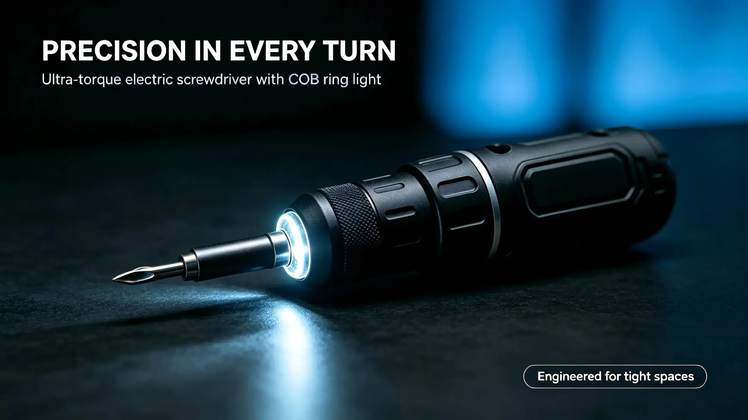
4.1 Ultra Thin and Flexible Form Factors
COB light engines can be built on Flexible Printed Circuit (FPC) substrates, reducing the total thickness to under 0.8mm. When combined with stainless steel or aluminum stiffener plates, a flexible COB module can wrap smoothly around curved tool barrels or fit inside narrow chuck collars without requiring deep internal cutouts.
4.2 Shadowless Annular (Ring) Illumination
In tools like electric screwdrivers or drills, discrete SMD LEDs cast multiple overlapping shadows around the bit. A continuous circular COB ring creates a 360° uniform light halo, eliminating bit shadows at the contact zone.
4.3 Simplified Mechanical & Assembly Integration
Because COB encapsulates all dies under a single phosphor canopy, OEMs do not need to design complex multi hole bezels, individual secondary lenses, or intricate wire routing. This reduces part counts (BOM) and lowers failure rates caused by vibration induced solder joint fractures.
4.4 Optimized Thermal Management
COB modules spread thermal energy across the entire substrate area rather than trapping heat in isolated hotspots. When mounted directly against a tool’s metal chassis or aluminum gear housing, heat dissipates efficiently, preserving diode longevity and lumen maintenance over extended duty cycles.
5. Application Case Studies
Case Study A: Precision Pen-Style Electric Screwdriver
Challenge: Traditional SMD LEDs required a bulky front nosecone, ruining the slim “pen-style” ergonomics and casting distracting bit shadows during delicate electronics repair.
COB Solution: An ultra thin 0.6mm circular COB module integrated directly into the front chuck housing
Result: Achieved a 360° shadowless light halo while maintaining a sleek 15mm tool diameter without adding any Z height.
Case Study B: Heavy Duty Industrial Hydraulic Crimper
Challenge: Severe tool vibration repeatedly cracked SMD solder joints, while concentrated glare blinded operators in dark utility vaults.
COB Solution: A metal stiffened, potting encapsulated COB flood module mounted flush with the working jaw.
Result: Increased vibration tolerance, passed drop testing, and provided a smooth, wide angle illumination field across the entire cable connection area.
6. Design & Selection Guide for OEM Engineers
When selecting or custom ordering a COB module for a power tool project, engineers should evaluate the following criteria:
[ Step 1: Define Target Area & Lux ]
↓
[ Step 2: Establish Z-Height & Curvature ] → Choose Substrate (FPC / MCPCB / Stiffener)
↓
[ Step 3: Match Drive Voltage & Current ] → Align with Tool Battery (3.7V / 12V / 18V)
↓
[ Step 4: Verify Thermal Dissipation ] → Ensure Conduction to Tool Body
Operating Voltage & Battery Match: Ensure the COB module’s forward voltage (Vf) aligns with the tool’s internal battery supply (e.g., single cell Li-ion 3.7V, or stepped down 12V/18V system rails) without requiring complex boost drivers.
Substrate Selection: Use FPC +Metal Stiffener for curved surfaces requiring mechanical rigidity at the solder pads, Ceramic for extreme thermal density, or MCPCB for flat, cost effective industrial floodlights.
Color Temperature (CCT) & CRI: Specify 5000K——6000K neutral/cool white for crisp task visibility, and CRI≥90 for inspection tools where wire color identification is critical.
7. Conclusion
COB technology is not meant to replace SMD LEDs in every application. For simple, low cost status indicators or unconstrained floodlights, SMDs remain a practical option.
But when the design calls for truly uniform illumination, shadow free task lighting, an ultra thin profile, or a more refined industrial look, COB light engines offer a clear engineering edge. By adopting custom COB solutions, OEM tool manufacturers can simplify housing designs, improve durability, and deliver a better, more user-centered product.
#COB for power tools #Custom COB module for OEM tools #Thin flexible COB backlight for tools #High CRI COB LED for inspection tools