
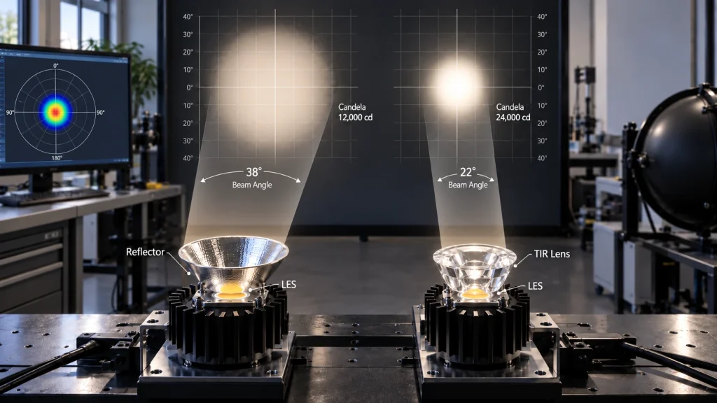
For a luminaire the COB LED and secondary optic must be selected as one system. I notice that a light emitting surface or LES generally gives a reflector or total internal reflection (TIR) optic more control. With flux and a suitable optic the LES can support a narrower beam and higher center beam candela. A larger LES will usually produce a wider beam or lower peak intensity when used with the same optic.
This is a screening rule, not a design answer and this screening rule is only a starting point. Source luminance, optic geometry, focal position, temperature, tolerances and beam shape also affect the result. The screening rule has to consider all those factors. I begin with the light that is needed on the target. Then I go backwards to look at beam angle, candela, optic geometry and LES because the screening rule tells me how changes, in candela or beam angle can alter the result. This screening rule lets you see how the source luminance and optic geometry work together to meet the LES requirement.
Start With LES Rather Than Package Size
The LES is the part that the eye can see, not always the material, the board, the window or the part that holds it open. Two COB LEDs can have the outside size but different LES sizes or shapes. A replacement that is picked just based on the board size can therefore change the beam.
LES position also matters. A change in emitting-plane height, centering or the source to optic gap can lead to a center, rings, spill or reduced efficiency. A broader high power COB LED selection guide can help check the thermal constraints, around this optical decision.
Understand the Relationship Between LES Beam Angle and Candela
Etendue Limits How Tightly Light Can Be Controlled
Etendue explains how the size of the source and the angle at which light comes out affect how concentrated that light is. A passive optic cannot make a large source behave like a smaller source.It cannot increase brightness without losing something.That something else could be the size of the opening the angle at which light is accepted how efficient the system’s the quality of the beam. A A small LES is useful when a light fixture needs a beam but still keeps a realistic size, for the optic. Look at how the LES size compares to the area and its shape. A larger reflector can help control the source better. A flat or small optic might not do well.
Beam Angle Describes Spread While Candela Describes Intensity
Beam angle is usually given as the angle, between the points where light intensity drops to half of its peak value. Field angle on the hand covers a wider area but at a lower brightness level. Don’t mix up these two terms. Even if two beams have the advertised angle they can still differ in how much light spills out how soft the edges are and how evenly the light spreads.
Candela tells you how bright a light is in a direction. Center beam candlepower or CBCP is the brightness at the center of the beam. The brightest spot, the hot spot in the middle. Two lights might give off the total lumens but one can still be much brighter, in the center if it focuses the light into a tighter narrower beam. For planning you can usually go with estimates based on light output or flux. That’s enough.. If you need precise results always rely on actual measurements. Real numbers matter when you’re getting serious. Actual beams aren’t perfectly even, so measured photometry is what gives you the true picture.
Convert the Application Into Optical Targets
Before you pick a COB LED lens or reflector first decide what area you want to light. Measure how far the fixture will be mounted, the size of the light spot how bright it must be how much light can spill over how even the light should be and how much glare is okay. With those numbers ready a vague ask, for a brighter or tighter beam turns into measurable goals that you can actually design and check.
For a circular beam, the first geometric estimate is:
Spot diameter = 2 x distance x tan(beam angle / 2)
If the target illuminance at the beam center is known, estimate the required intensity with the inverse square relationship:
Required candela = target lux x distance squared
These calculations do not account for optical losses, nonuniformity, tilt, obstructions, thermal droop, or the difference between peak and average intensity. Add realistic margin and validate the assembled luminaire.
Choose Between a Reflector and a TIR Optic
Use a Reflector When Aperture and Beam Character Fit
A reflector redirects light after it leaves the source. Its aperture, depth, profile, finish, and source position determine capture and the transition from center to spill. Reflectors suit fixtures with enough depth and designs that need a familiar spotlight distribution.
If the lens or reflector is too big for the way the light is aimed the rays can clash at angles. Making the reflector deeper or giving it an opening can give more control but limits, in the physical space and the need to reduce glare may stop that from being possible.
Use TIR Optics When Compact Capture and Defined Distribution Matter
A TIR optic uses entrance refraction and total internal reflection to capture a range of source angles, in a small component. It can create spot, medium, wide, oval or other types of distributions. The cavity needs to clear the emitting surface. The optic needs to be placed in the correct position.
An optic designed around one LES, radiation pattern or emitting height might not keep its catalog beam with another COB LED. Consider compatibility data as a starting point because holders, windows, gaps, temperature and drive current can affect the outcome.
Match the COB LED and Optic Step by Step

- Define the target plane. Set distance, spot size, center illuminance, uniformity, spill, and glare limits for the actual application.
- Convert the target into beam angle and candela. Use geometric and inversesquare estimates to establish a practical range rather than a single theoretical value.
- Screen the LES against the optic. Compare LES diameter or dimensions, emittingplane height, radiation pattern, and position with the reflector aperture or TIR entrance cavity.
- Check the complete fixture. Confirm holder clearance, mounting datum, thermal interface, driver current, front glass, bezel, and enclosure surfaces that can clip or redirect light.
- Prototype, than one pairing. A larger optic, a different beam family or a smaller LES may meet the target with better uniformity or tolerance margin.
Build a Prototype and Verify the Beam
The full system, including the COB LED drive current, holder, optic, thermal stack, front cover and enclosure needs to be checked as a whole. Tests should be performed after the system reaches thermal steady state.The same production mounting reference and tolerance stack should be used. The tests should measure things like peak candela, beam angle, field angles total light output, spill light, any strange effects and the light level on the target area. Photometric evaluations have shown that beam angle and candela should be considered together. They can’t just be guessed from how power the lamp uses or how much light it gives off. Limits, for passing the production tests should be set.. When needed an IES file or a LDT file should be asked for.
What to Request From a COB LED Supplier
Ask for LES dimensions and shape, emitting plane height, a drawing with the optical center, radiation pattern, flux at the intended current and temperature, and applicable tolerances. Also request electrical data, thermal limits, color specifications, and the conditions behind photometric claims.
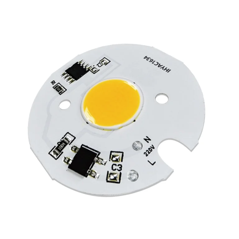
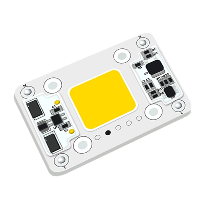
IHY Lighting lists high-power COB light engines and custom COB development for evaluation within a complete optical system. An RFQ should include target beam angle, required CBCP or lux and distance, optic diameter and depth, LES limit, driver conditions, cooling method, fixture drawing, sample quantity, and expected volume. Confirm the pairing through drawings, samples, and system photometry.
Conclusion
The size of the les sets a limit on how well you can control the beam, but it doesn’t dictate the optic by itself. Make sure the source area and its location match the reflector or total internal reflection (TIR) shape. Then work out the beam and candela the job actually needs, and check the fixture once it has reached steady state temperature. If you’re considering a standard or custom setup, talk through your lighting goal with the engineering team. Give them the fixture drawing, working distance, desired light pattern, required brightness, available optic space, power limits, and thermal conditions.
FAQs
Does a Smaller LES Always Produce Higher Candela?
No. A smaller lens can improve the potential, for a narrow intense beam but actual candela also depends on source flux and luminance optic efficiency, aperture, alignment, drive current, temperature and beam shape. Compare measured system photometry under the intended operating conditions.
Can the Same Reflector Work With Two COB LEDs of the Same Package Size?
It might fit in a way and still create a different beam. Check the LES measurements the height of the emitting plane, the center the pattern of light coming out and the shape of the dome or window. Test the beam angle, CBCP, spill and any unwanted effects again after changing the source.
Is Beam Angle Enough to Compare Two Optical Systems?
No. Review CBCP, field angle total delivered lumens, uniformity, spill, cutoff and intensity distribution. I have seen that two beams, with the 50-percent angle can look and perform differently because beam peak shape and beam edge transition are different.
What Information Is Needed Before Selecting a TIR Optic?
Provide the COB LED model or the full LES geometry, the height from which it emits light the pattern it radiates the target beam it produces the size of the optic and how deep it can go. Also provide how the holder is arranged the distance it works best at and how strong the light needs to be. Add details, about the heat and the power supply conditions so the sample looks like the light fixture.