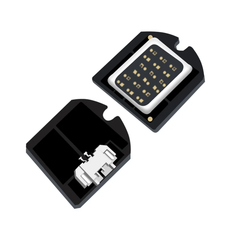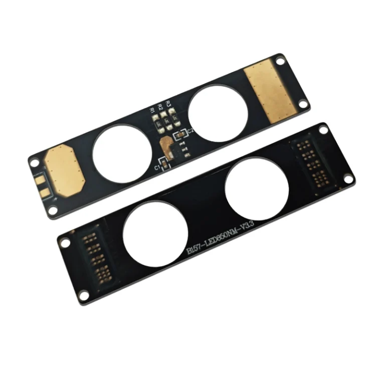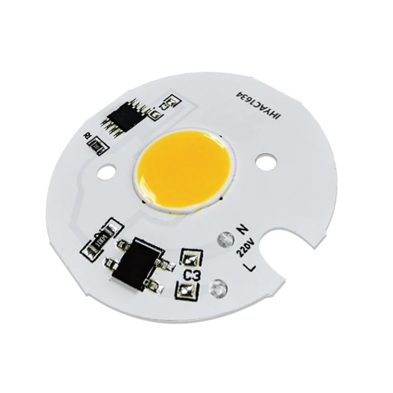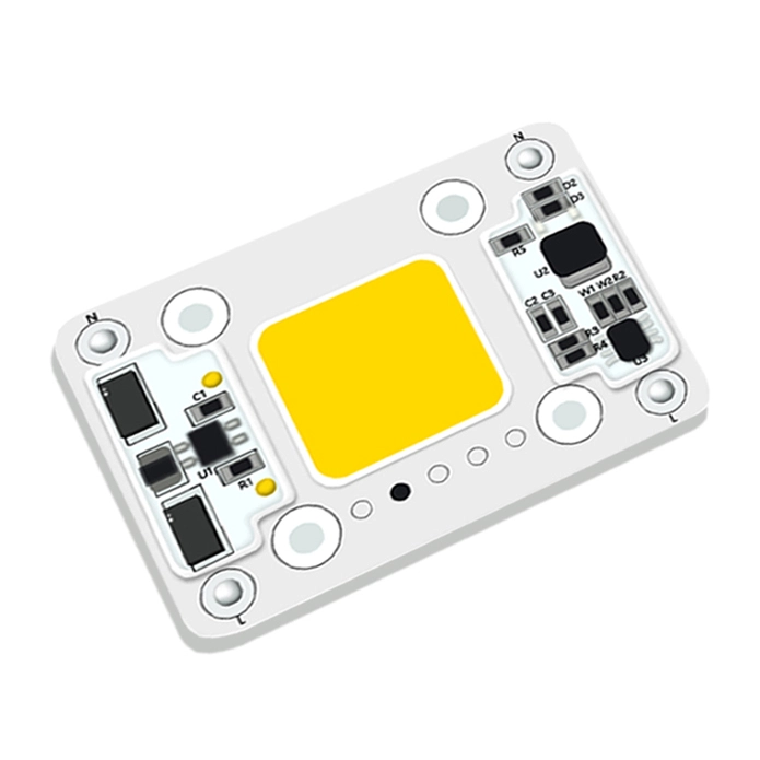



In machine vision, lighting is not an accessory, it’s part of the measurement. The correct geometry determines whether a camera sees an edge, a readable mark, a surface defect or only glare. Ring, backlight, bar, and coaxial illumination each solve a specific imaging problem. Selecting among them starts with the feature to be inspected the surface finish, the camera axis, the working distance and the motion of the production line.
This guide covers how each technique works, where it usually fits, and what to check before you commit a custom light to an inspection station. Shenzhen IHY Lighting develops / customs COB LED, LED module and application oriented lighting solutions; its published product range covers COB LED and LED modules for OEM integration but the final geometry, wavelength, and interface always come down to the inspection job.
Start With the Image Task, Not the Fixture Shape
Start by defining what the camera actually needs to see. A gauging task usually needs a high contrast silhouette or a repeatable edge. A print or code reading task needs even contrast across the field of view. Scratch, burr, dent and raised text inspection often needs controlled scattering. Reflective metal, glass and polished plastic require a geometry that keeps the reflection away from the lens or spreads it into a predictable field.
Before we choose a light, record the part material and finish, the feature size and color, and the optical and mechanical constraints. Ambient light, enclosure space, and heat limits also matter. A light that produces a good bench image can fail on a moving line if it cannot be strobed, synchronized, or mounted at the required distance. Put these conditions into the lighting spec from the start. Don’t leave them to be fixed after you’ve bought the light.
Ring Lighting for General Front Illumination
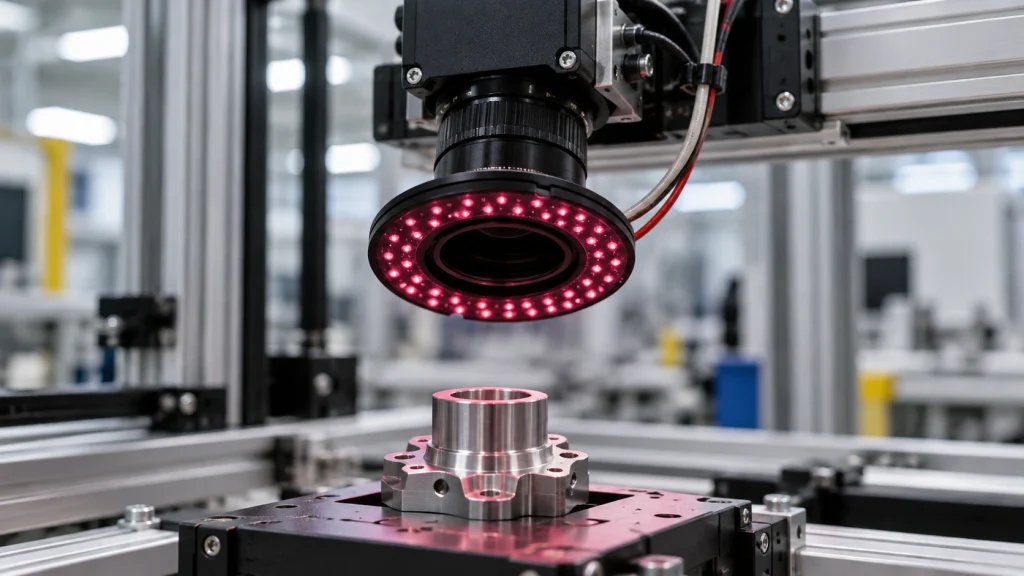
A ring light places LEDs around the camera lens and sends light toward the part from a near axis, front facing direction. Its circular arrangement gives broad coverage and is often a practical starting point for flat or gently curved parts, assembly presence checks, label reading, and general surface inspection. Different working distances and diffusion treatments change how much shadow, texture, or specular reflection reaches the sensor.
Ring illumination is useful when the part must be lit from several azimuths at once, but it is not automatically shadow free. Recesses, tall edges, and glossy surfaces can still create uneven highlights. A low angle ring or segmented control can emphasize edge texture, while a diffused ring can reduce harsh point reflections. For an OEM station, specify the inner diameter, outer envelope, working distance, beam angle, color or wavelength, diffuser, trigger interface, and access for the lens and cable routing.
Backlighting for Silhouettes and Dimensional Edges
Backlighting places the source behind the part, opposite the camera. The camera sees the object as a dark silhouette against a bright field. This separation is valuable for outline measurement, hole and slot detection, presence or absence, position checks, and dimensional gauging. Because the image depends mainly on the boundary, small changes in surface color or texture often matter less than they do with reflected light inspection.
The trade off is deliberate: surface markings, scratches, and color information largely disappear. Use a backlight when the edge is the measurement target, not when the inspection depends on top surface appearance. Mechanical alignment is critical. The source must fill the intended field without exposing gaps around the part, and the camera, part plane, and light plane must remain stable as the line runs. Verify edge sharpness at the actual lens aperture and exposure settings rather than judging only by brightness.
Bar Lighting for Directional and Long Format Coverage
Bar lights use one or more linear LED assemblies positioned beside, above, below, or at an angle to the part. They are flexible when the camera cannot be surrounded by a ring or when the target is long, wide, recessed, or moving through a constrained inspection window. Multiple bars can be arranged as a two sided, four sided, or opposed angle system, with each channel tuned for a different feature.
The main design variable is direction. A shallow angle can make scratches, raised edges, knurling, or embossed text scatter light into the camera. A higher angle can provide broad bright field coverage for flat faces. Bar spacing and overlap determine uniformity, while the bar length and diffusion determine whether the ends of the image are darker than the center. For OEM equipment, confirm mounting rigidity, adjustment range, cable exit, heat path, strobe response, and whether independent channels are needed for alternate recipes.
Coaxial Illumination for Flat Reflective Surfaces
Coaxial illumination sends light along the camera’s optical axis, typically through a beam splitting arrangement. The result is a controlled, nearly on axis field that can reveal contrast on flat, mirror like, or highly reflective surfaces where an angled source would produce a bright spot or a reflection of the fixture. It is commonly considered for glass, polished metal, wafers, films, and flat code or mark inspection when surface geometry is controlled.
Coaxial designs are sensitive to working distance, optical path, and the exact flatness and finish of the target. Curved parts can still produce gradients or reflections outside the useful field. Check the beam splitter envelope against the lens, camera mount, and enclosure, and test the complete optical stack with the production material. If a mark is low contrast, wavelength and polarization may matter as much as the housing geometry; those choices should be validated with images from representative parts.
How to Choose Between the Four Techniques
Use this decision sequence for an OEM inspection system:
- If the target is an outline, hole, slot, or external dimension, start with backlighting and verify silhouette contrast.
- If the target is a broad front face or a general presence check, test a ring light first, then adjust diffusion and angle for glare.
- If the target is long, recessed, or sensitive to directional texture, test bar lights from two or more controlled angles.
- If the target is flat and highly reflective, test coaxial illumination before adding more frontal intensity.
- If one image cannot expose every feature, consider segmented channels, multiple exposures, filters, or a second lighting geometry rather than forcing one fixture to do incompatible jobs.
OEM Specification and Validation Checklist
A useful RFQ includes the part drawings or samples, material and surface finish, inspection features, camera and lens information, field of view, working distance, cycle time, trigger signal, enclosure limits, and expected quantity. Ask the lighting supplier to state which values are confirmed and which depend on the final optical test. Important verification points include illumination uniformity, repeatability across units, strobe timing, thermal behavior, wavelength stability, diffuser or polarizer compatibility, mounting datum, connector and driver arrangement, and access for maintenance.
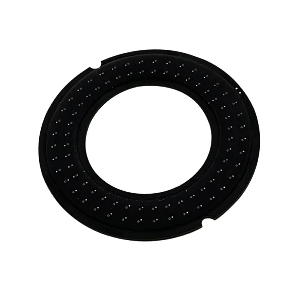
IHY’s public site presents custom COB LED and LED module capabilities, plus application oriented LED solutions. These pages are useful starting points when an inspection builder needs a custom light engine or integrated module rather than an off the shelf lamp. The exact machine vision fixture, optical performance, and interface should be confirmed against drawings, samples, and a documented test plan. For project scoping, contact the technical team with the part, feature, camera, dimensions, operating conditions, and quantity.
Conclusion
Direct reflections are usually the culprit when you get hotspots or unstable contrast. How you fix it depends on the finish: diffusion, a different angle, polarization, segmented lighting, or going coaxial, each works for certain surfaces. Test with real parts before you commit.
FAQs
Which machine vision light is best for dimensional measurement?
Backlighting is often a starting point for silhouettes, edges, holes and outer dimensions because the boundary is separated from the background. But the final result still depends on part geometry, lens resolution, alignment and the required tolerance.
Can a ring light inspect shiny metal?
Direct reflections can cause hotspots or unstable contrast. Diffusion, angle, polarization, segmentation, or coaxial geometry can help produce repeatable images for a given finish.
When should bar lights be used instead of a ring light?
Bar lights are typically used for elongated parts, recessed targets, or surfaces with directional texture. They are also useful when the camera mount occupies space that would prevent a ring light from fitting. You can angle several bars to pick out different features.
What should an OEM send for a lighting quote?
Please provide the part drawings, material and finish, known defects or tolerances, camera and lens specifications, field of view, working distance, cycle time, trigger method, enclosure limits, and expected quantity.