



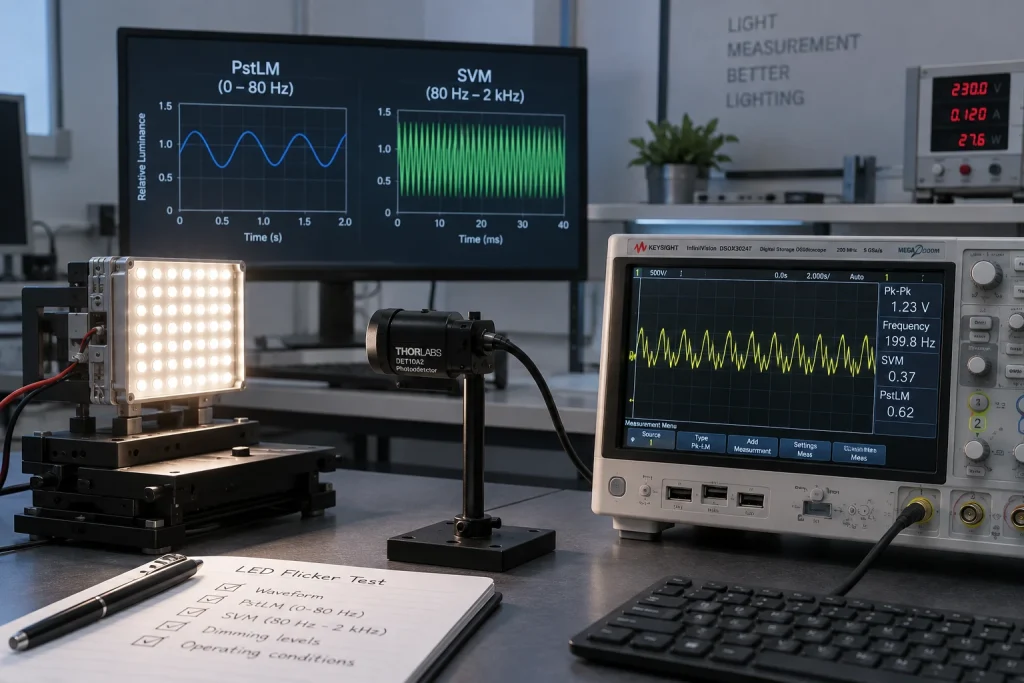
IEEE 1789-2015 became an Inactive Reserved Standard on March 26, 2026. For LED OEMs, LED flicker testing after this change should no longer treat its frequency versus modulation guidance as the only current answer. A practical specification now needs to identify the market requirement, measure the optical waveform, report PstLM for visible flicker and SVM for stroboscopic effects, and test the complete source driver control system at the operating points customers will actually use.
The change does not make every earlier IEEE based report useless. It changes how teams describe evidence. The official IEEE status page identifies IEEE 1789-2015 as inactive and reserved. Buyers should therefore distinguish a legacy design reference from a current regulatory test method or contractual requirement.
What the Inactive Status of IEEE 1789 Changes
IEEE 1789 was a recommended practice for modulating current in high brightness LEDs to mitigate known potential health risks. It expressed recommended modulation limits as a function of frequency. Its inactive status is an administrative standards status. It is not a product recall, a declaration that every design using it is unsafe, or proof that a luminaire passes another market’s rules.
Existing drawings and purchase specifications may still cite IEEE 1789. Keep that requirement when a contract calls for it, but do not label a 2026 product simply as compliant without stating the edition, metric, operating condition, and acceptance criterion. New specifications should use recognized temporal light artifact metrics and the rules that apply to the destination market. Where no regulation governs the product, the customer can still set project limits for comfort, motion visibility, cameras, or machine vision.
What PstLM and SVM Measure
PstLM and SVM answer different perceptual questions. PstLM estimates short-term visible flicker, with the calculation commonly based on the light flickermeter method in IEC TR 61547-1. SVM estimates the visibility of the stroboscopic effect when an observer or object moves, using the method described in IEC TR 63158. Each metric applies frequency weighting to the measured optical waveform, so neither is interchangeable with percent flicker or flicker index.
| Measure | What it evaluates | Typical evaluation band | How to use it |
| PstLM | Perceived short-term visible flicker | Approximately 0 to 80 Hz | Apply the specified project or market limit |
| SVM | Stroboscopic visibility during motion | Approximately 80 Hz to 2 kHz | Apply the specified project or market limit |
| Percent flicker and flicker index | Basic waveform modulation summaries | Not perceptually weighted across frequency | Use for diagnosis unless a contract requires them |
The EU ecodesign regulation for light sources and its amendments use PstLM and SVM for defined products. For in scope LED and OLED mains light sources, the post transition full load reference values commonly applied in 2026 are PstLM at or below 1.0 and SVM at or below 0.4. Product scope, exemptions, and the current consolidated legal text must still be checked. These regulatory values are not universal design guarantees and should not be copied into an unrelated market without review.
How to Build an LED Flicker Test Plan
Define the Market and Product Scope
Start with the destination market, product category, intended use, and contract. Identify whether the test applies to a lamp, luminaire, replaceable light source, separate driver, or integrated light engine. Record the required regulation or voluntary specification and its edition. A US OEM may use PstLM and SVM as procurement metrics even when an EU ecodesign requirement does not apply, but the report should say that clearly.
Measure the Optical Waveform
Measure light output with a calibrated photodetector and acquisition system whose bandwidth, sampling rate, dynamic range, and analysis software suit the required method. Control detector position, illuminated area, ambient light, supply voltage and frequency, warm up time, temperature, and stabilization. Capture the optical signal rather than inferring flicker from electrical current alone. Retain the raw waveform when possible so unexpected results can be investigated.
Test Dimming Modes and Operating Corners
The LED source, driver, controller, load, wiring, and firmware create the final waveform together. Test rated output, intermediate levels, the minimum stable dimming level, dim to off behavior, and any PWM or constant current reduction modes. Repeat at relevant input voltage limits and after thermal stabilization. Multichannel products also need representative channel mixes because synchronization and current balance can change with color or CCT settings.
A full load regulatory result can coexist with poor low end dimming or camera banding. Add application tests at the frame rates, shutter settings, motion speeds, and control scenes the product must support. Smartphone video can reveal a problem, but it cannot replace a calibrated PstLM or SVM measurement because camera exposure and rolling shutter alter what appears on screen.
Report Traceable Results
A useful report names the device under test, driver and controller, firmware, supply conditions, dimming command, stabilization time, ambient temperature, detector setup, instrument model, calibration status, software version, algorithm, and standard edition. Report PstLM and SVM for every required operating point and attach the optical waveform or frequency analysis when requested. State pass or fail only against an identified limit.
Turn Test Results into LED Module Requirements
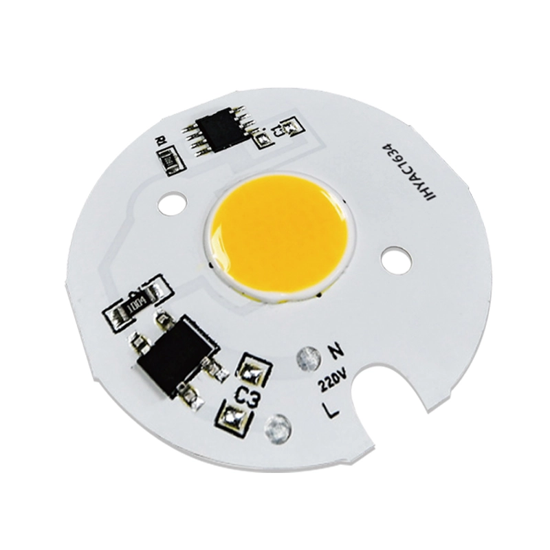
Flicker performance is a system requirement, not an isolated LED-chip property. The sourcing specification should bind the COB or LED array to its driver topology, current range, voltage window, dimming interface, controller, thermal conditions, and optical test points. A change in driver component, firmware, capacitor value, PWM frequency, or channel architecture can justify retesting even when the light emitting package is unchanged.
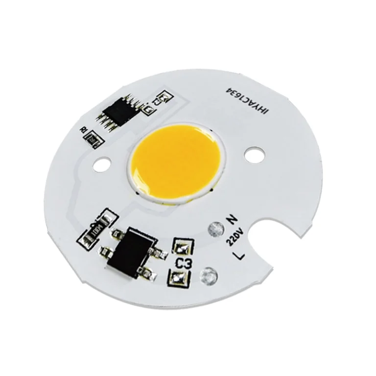
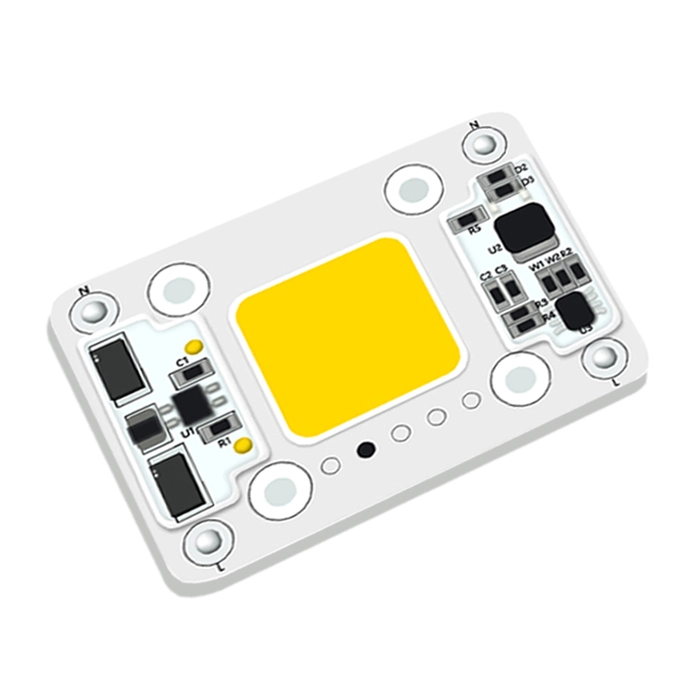
IHY’s integrated LED module range includes AC, DC, cinematic, studio, and other module categories. The published COB LED driver selection guide explains why current, the full forward voltage range, dimming, protection, and temperature must be evaluated together. For camera facing products, IHY’s stage lighting selection guide adds frame rate, shutter, fade to black, acoustic, and thermal checks. These pages support specification work; final suitability still depends on testing the intended assembly.
What to Put in the RFQ
Ask suppliers and test laboratories to quote against the same evidence package:
- Product type, destination market, application, operating environment, and required standard editions
- LED or COB model, driver model or topology, input range, regulated current, voltage window, and channel configuration
- Dimming interface, control protocol, firmware, PWM frequency where relevant, and minimum required output level
- Required PstLM and SVM limits at named operating points, plus any camera or motion acceptance tests
- Instrument, calibration, test geometry, stabilization, ambient conditions, raw waveform, and report format
- Change-control rules that identify which substitutions or firmware revisions trigger retesting
Conclusion
IEEE 1789’s inactive status closes one chapter in LED flicker guidance, but it does not create a single universal replacement rule. A defensible 2026 specification identifies the applicable market requirement, uses PstLM and SVM for their intended perceptual effects, preserves traceable optical data, and tests the complete light engine across dimming and operating limits. That approach gives engineering and procurement teams evidence they can compare instead of relying on an undefined flicker free claim.
Frequently Asked Questions
Does Inactive Mean IEEE 1789 Cannot Be Used?
No. A contract or internal design rule may still reference IEEE 1789-2015. Its inactive status means teams should not present it as an active current standard without qualification. State the edition, purpose, and acceptance criterion, then add current market-specific tests where required.
Are PstLM and SVM Direct Replacements for IEEE 1789?
Not exactly. IEEE 1789 recommended modulation practices as a function of frequency. PstLM and SVM are perceptually weighted metrics calculated from an optical waveform. They support clearer measurement and regulation, but the applicable limit still comes from a law, program, contract, or project specification.
Can Percent Flicker Predict PstLM or SVM?
No reliable one to one conversion exists. Waveforms with the same modulation percentage can produce different perceptual results because frequency, shape, duty cycle, and harmonics matter. Use percent flicker and flicker index as supplementary diagnostics, not substitutes for required PstLM or SVM results.
Should a Dimmable LED Be Tested Only at Full Output?
No. A regulation may define a full load test, but customer use can expose worse modulation at intermediate or minimum dimming levels. Test the specified legal point and the operating points that matter for comfort, motion, cameras, controls, and thermal behavior.
For an application review, provide IHY with the LED or COB model, driver data, input supply, control method, dimming range, target market, enclosure and temperature conditions, sample quantity, and required test limits. Use these details to request an LED module compatibility review and determine whether a standard module, modified electrical design, or integrated light engine should be evaluated.