



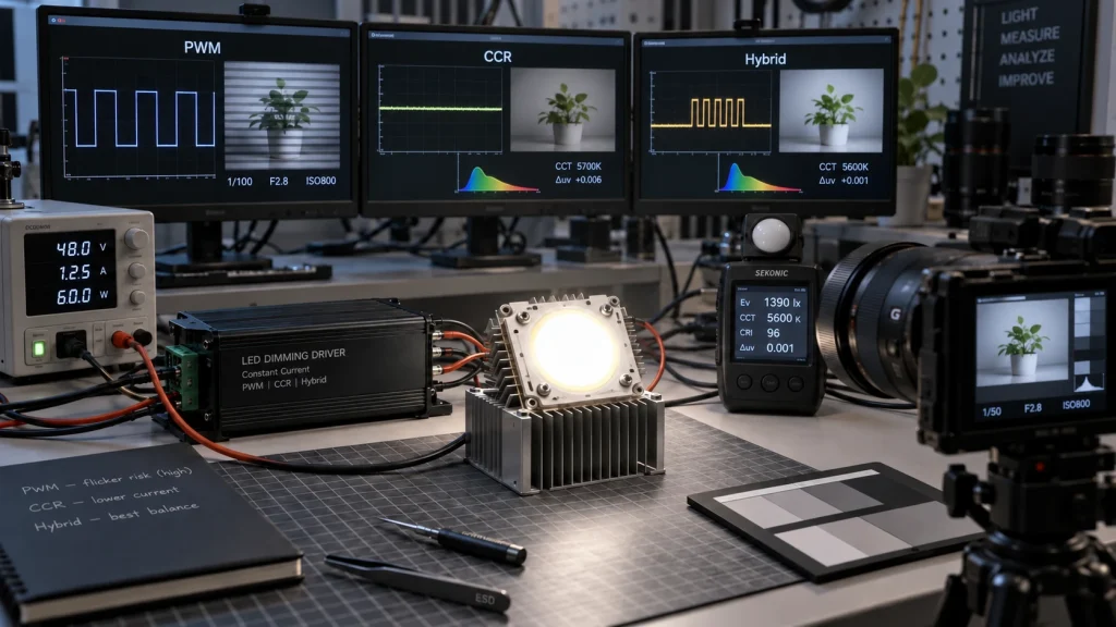
PWM LED dimming, current reduction (CCR) and hybrid dimming can all control a high power COB LED but each one focuses on different risks. PWM LED dimming usually keeps the LED at its current spectral condition while the duty cycle is changed. Constant current reduction (CCR) gives light by lowering the current. Hybrid dimming mixes the two methods to broaden the dimming range. The best choice depends on the camera settings that are used the acceptable amount of flicker and phantom array risk how much color shift is allowed the lowest output required, how efficient the driver is, the limits and the control interface that is used. No single method is automatically free of color change or inefficient, at every operating point.
How PWM, CCR, and Hybrid Dimming Control COB Current
PWM Dimming: Full Current Pulses
Pulse width modulation switches LED current between off and a defined on state. Pulse width modulation makes the average light output fall as duty cycle decreases. Pulse width modulation keeps the current during each pulse normally near the selected operating level. Pulse width modulation is a way to control LED light. This can retain chromaticity closer to the full output condition, but the modulation depth is high and low duty cycles demand accurate pulse timing. Peak current must remain within the COB and driver limits.
CCR Dimming: Lower Continuous Current
CCR, also called analog or amplitude dimming, lowers the regulated DC current. It avoids on off pulses, which can simplify camera behavior, but the LED junction now operates at a different current density. Luminous efficacy, forward voltage, phosphor conversion, CCT, chromaticity, and driver regulation can all change as current falls. Deep dimming may also reach the driver’s minimum controllable current or reach the driver’s dropout zone.
Hybrid Dimming: Two Control Regions
A hybrid driver uses CCR over one part of the range and PWM over another. A common objective is smooth, efficient control at medium to high output with a wider low end range than CCR alone. The crossover point isn’t fixed. It changes based on how your driver’s designed. We need to check for a brightness step color jumps, sounds we can hear flicker changes and channel mismatches in multi-channel COBs. Each of these matters when tuning the crossover. Make sure you look for them one, by one. It’s not a one-size-fits-all thing. Your setup will decide what works best.
| Method | Flicker and cameras | Color behavior | Main design risk |
| PWM | Frequency, duty cycle, and waveform interact with exposure. | Often closer to the on state color point. | Banding, EMI, pulse accuracy |
| CCR | No intentional pulses, but ripple can remain. | Current dependent spectral shift must be measured. | Low current regulation |
| Hybrid | Behavior changes across the crossover. | Can limit shift if regions are chosen well. | Transition artifacts |
Flicker and Camera Banding Are System Level Outcomes
Flicker, stroboscopic effects and phantom arrays are all results of light that changes over time. The DOE review of temporal light modulation emphasizes that the LED, driver, and control form one system. A frequency that seems okay to someone watching might still cause issues when things are moving or when a camera is used. The IEEE 1789-2015 recommended practice provides historical risk guidance for modulated high brightness LEDs; current project requirements and applicable standards should also be checked.
Camera banding occurs when LED modulation matches exposure time, frame rate, shutter angle or shutter speed rolling shutter readout and phase. Raising the PWM frequency usually makes things better. The frequency by itself is not something that can be simply accepted or rejected. Ask about the modulation frequency, the pulse width the duty cycle resolution, the modulation depth and the waveform, at every dimming level. Then test the intended cameras in their real modes. CCR can reduce this risk, yet converter ripple, control loop instability, or line frequency modulation can still produce bands.
Color Shift and Low Level Light Quality
CCR changes the LED operating current, so the spectrum can move as the dimming level changes. The direction and magnitude depend on die, phosphor system, temperature, drive range, and optical measurement conditions. PWM holds the on state current more constant, but junction temperature changes, pulse shape, current overshoot, and very narrow pulses can still alter measured color or output. Hybrid control trades a controlled amount of current related shift against lower modulation exposure.
Specify acceptance limits for CCT, chromaticity or Delta u’v’, CRI where relevant, and channel tracking at defined output levels. Measure after thermal stabilization with the production driver, optics, heat sink, and enclosure. Visual inspection alone is not enough for tight color requirements.
Efficiency, Thermal Load, and Electrical Noise
CCR may improve LED efficacy at reduced current, but system efficiency also includes the driver’s conversion losses, bias power, and light load behavior. PWM reduces average LED power with duty cycle while repeatedly switching current, so switching losses and electromagnetic interference can increase. A hybrid scheme can keep the driver in a favorable regulation region, although its extra control complexity does not guarantee a net efficiency gain.
Compare input power, LED current waveform, case temperature, and useful optical output at full, mid, minimum, and transition levels. Do not infer thermal safety from average power alone: verify peak current, transient overshoot, hot restart behavior, cooling, wiring, and driver derating. The appropriate operating point depends on the complete light engine.
Choose the Dimming Method From the Application
- If you are shooting video or driving industrial automation cameras, go with high-frequency PWM or pure CCR to stay band-free.And high speed imaging: prioritize camera tests across every frame rate and exposure mode; evaluate CCR or sufficiently high frequency PWM with measured waveforms.
- Stage and entertainment lighting: balance camera compatibility, deep fades, response speed, channel matching, and control latency. Hybrid control may be useful only if its crossover is unobtrusive.
- Architectural and task lighting: define temporallight modulation limits, smooth low end behavior, acoustic noise, energy performance, and color consistency at representative temperatures.
- Battery or thermally constrained equipment: Don’t just look at datasheet specs. We should measure real system efficacy: lux delivered per system wattand component temperature over the duty cycle, not just nominal driver efficiency.
Start with the COB’s rated current, complete forward voltage range, thermal boundary, and channel arrangement. The available high power COB LED module range establishes real source options; the high power COB LED module selection guide helps translate the application into electrical, optical, thermal, and mechanical requirements.
Specify and Validate the COB LED Dimming System
Use high power COB LED driver selection as the electrical foundation, then add dimming specific acceptance criteria. We should record the control interface and logic levels, PWM input limits, analog range, minimum output dim to off behavior startup sequence fault response, cable length, ambient temperature and target camera settings. For control you should document the crossover level and hysteresis.
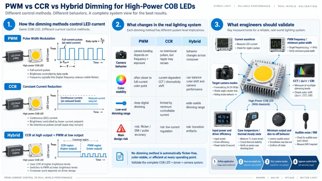
Validate a representative assembly at cold start and thermal steady state. Sweep brightness slowly and step between critical levels while recording current waveform, optical waveform, input power, case temperature, chromaticity, and camera output. Repeat at input voltage and temperature limits. Production approval should define limits. Production approval should not use labels, like flicker free camera safe or zero color shift.
Conclusion
PWM is often strongest where color stability and deep digital control matter; CCR is attractive where continuous light and camera behavior dominate; hybrid control can extend range but introduces a crossover to validate. The best architecture is the one that meets optical, temporal, thermal, electrical, and imaging limits in the finished system. To request a COB LED dimming fit check, provide the COB model, driver data, control signal, dimming range, camera settings, thermal conditions, drawings, sample quantity and expected volume, to IHY Lighting.
FQA
Is CCR the same as constant current driving?
Not exactly. A COB LED normally needs a constant current driver. We can think of CCR as turn down the tap, it smoothly reduces the continuous DC water flow (current) to dim the light.
Does high frequency PWM guarantee band–free video?
No. Results depend on frequency, modulation depth, pulse shape, exposure, frame rate, rolling shutter timing, and phase. Test every required camera mode with the finished system.
Which method gives the least COB LED color shift?
PWM often keeps the on state spectrum closer to the selected full current point. Actual color stability still depends on current waveform, temperature, LED construction, optics, and measurement conditions.
Why use hybrid dimming?
Hybrid control can combine smooth, efficient operation over one region with a wider low end range in another. Its crossover must be checked for brightness, color, flicker, and noise discontinuities.