The thermal management design of high-power LED modules is a core element to ensure their long-term stability and efficient operation. The following are the design ideas and key technical points of a set of systems:
Temperature control: The junction temperature (Tj) should be kept within the range allowed by the device specification, usually below 120℃. Because for every 10℃ temperature rise, the luminous efficacy will decrease by 3-5% and the lifespan will be halved, it is necessary to strictly avoid the problems of luminous efficacy attenuation and shortened lifespan.
Uniform temperature performance: The temperature gradient between chips should be minimized as much as possible to prevent the occurrence of local hotspots.
Thermal path optimization: To achieve efficient heat conduction from the chip to the environment and ensure that heat can be dissipated in a timely manner.
2.1 Substrate materials
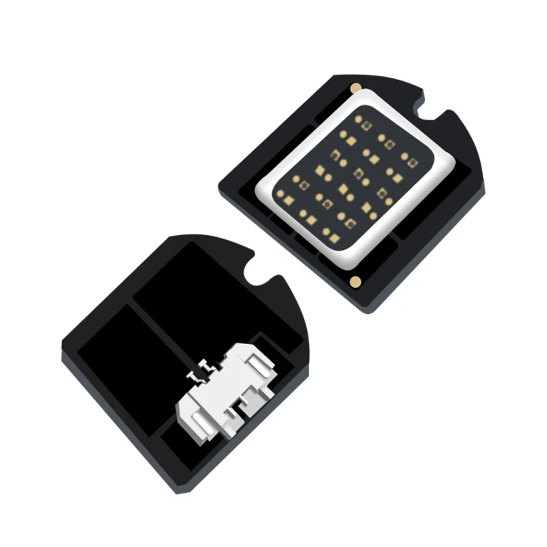
Ceramic substrate
Al₂O₃ (aluminum oxide) : It has a relatively low cost, approximately 0.5 to 1 yuan per cm², with a thermal conductivity ranging from 24 to 28 W/(m·K), making it suitable for medium and low power scenarios.
AlN (Aluminum nitride) : Its thermal conductivity can reach 170-230 W/(m·K), but it is relatively expensive, costing 3-5 yuan /cm², and is suitable for high power density scenarios. 10 W/mm².
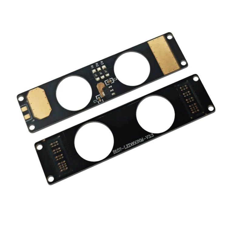
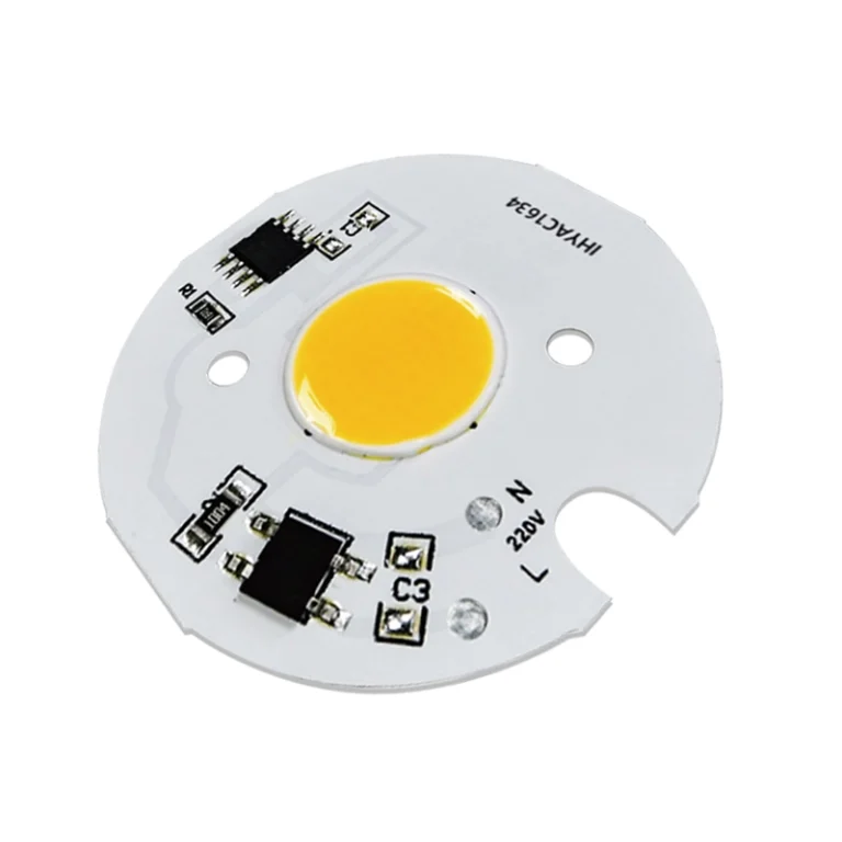
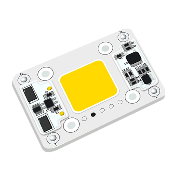
Metal substrate (MCPCB) : Taking aluminum substrate as an example, its thermal conductivity is 1-3 W/(m·K), and it is used in combination with an insulating layer. Although the cost is relatively low, the thermal resistance of the insulation layer needs to be optimized.
2.2 Heat Dissipation Structure
Passive heat dissipation
Finned heat sink: It mainly relies on natural convection to achieve heat dissipation. Among them, the ratio of fin height to spacing (usually between 5:1 and 10:1) and the surface blackness (which can be enhanced through anodic oxidation treatment to increase the emissivity) are the key factors.
Heat pipe/vapor chamber: Utilizing the principle of phase change heat transfer, its thermal conductivity can reach 5000 W/(m·K), making it highly suitable for eliminating local hotspots.
Active heat dissipation
Fan forced convection: The air volume needs to match the air resistance of the radiator. The typical air volume is 0.1-0.5 CFM/W.
Liquid cooling system: Microchannel cold plates (water-cooled) can handle The heat flux density is 100 W/cm², but the entire system is rather complex.
Thermal grease: The thermal resistance is between 0.1 and 0.5 ℃·cm²/ W. However, it should be noted that after long-term use, it may age and dry up.
Phase change material (PCM) : With a thermal resistance of 0.05-0.2 ℃·cm²/W, it undergoes phase change at 45-60℃, thereby filling the voids.
Thermal conductive gasket: It belongs to elastic materials, with a hardness ranging from Shore 00 30 to 50. It can compensate for assembly tolerances, and the thermal resistance is between 0.3 and 1.0 ℃·cm²/W.
Simulation tool:
Three-dimensional models can be established using ANSYS Icepak or FloTHERM, with a focus on the thermal resistance network (the total thermal resistance θ_ja from the junction to the environment).
Parametric analysis was conducted on parameters such as fin thickness and spacing to study their influence on the heat transfer coefficient (the natural convection heat transfer coefficient is approximately 5-10 W/(m²·K)).
Experimental verification:
Infrared thermal imaging: This technology can precisely locate hot spot areas, with a measurement accuracy of ±2℃.
Junction temperature measurement: Calibration was carried out using the forward voltage method (Vf-Tj coefficient approximately -2 mV/℃).
Drive current optimization: When Tj > At 85℃, the starting current derating measures are implemented, for example, with a reduction of 0.5% per ℃.
Optical matching: By means of secondary optical design, ineffective heat generation is reduced, such as improving the efficiency of the reflector cup. 90%.
Structural layout
The multi-chip modules are arranged in an interlaced manner with a spacing of ≥3 mm, thereby reducing mutual thermal coupling.
The power drive circuit is physically isolated from the LED to reduce the superposition of heat sources.
Accelerated aging test
The test was conducted for 1000 hours under the condition of 85℃/85%RH, and the light attenuation should be… Five percent.
Carry out temperature cycling tests (-40℃ to +125℃, 100 cycles) to examine the CTE matching of the materials.
Failure mode analysis
For the problem of solder joint fatigue (Cokendall vowel), it can be improved by using Sn-Ag-Cu solder.
For the carbonization problem of phosphor, it is necessary to control the surface temperature of the blue light chip. 150℃.
Hierarchical heat dissipation design
Low-power segment 50W) : Heat dissipation is achieved through an aluminum substrate combined with natural convection.
Medium power range (50-200W) : A heat dissipation solution combining heat pipes and forced air cooling is adopted.
High power segment (200W) : Consider using liquid cooling or semiconductor refrigeration methods.
Modular design: Allows for the expansion of heat dissipation capacity in the later stage, such as reserving fan interfaces, etc.
Sample solution: 200W LED module
Substrate: AlN ceramic is selected, with dimensions of 40mm×40mm and a thickness of 1mm.
Radiator: It adopts 6063 aluminum alloy fins, with dimensions of 200mm×150mm×50mm, and the surface is blackened.
TIM: Use graphene to fill the phase change material with a thickness of 0.2mm.
Thermal resistance: θ_jc = 0.8℃/W, θ_ca = 1.2℃/ W. From this, θ_ja = 2.0℃/W can be obtained.
Temperature rise: ΔT = 200W×2.0℃/W = 40℃. When the ambient temperature is 25℃, Tj = 65℃.
Through multi-physics field collaborative design and full life cycle thermal management, the luminous efficacy of LED modules can be achieved. 150 lm/W, lifespan 50,000 hours (L70 standard) of industrial-grade performance. The specific parameters still need to be iteratively optimized in combination with optical and electrical designs.